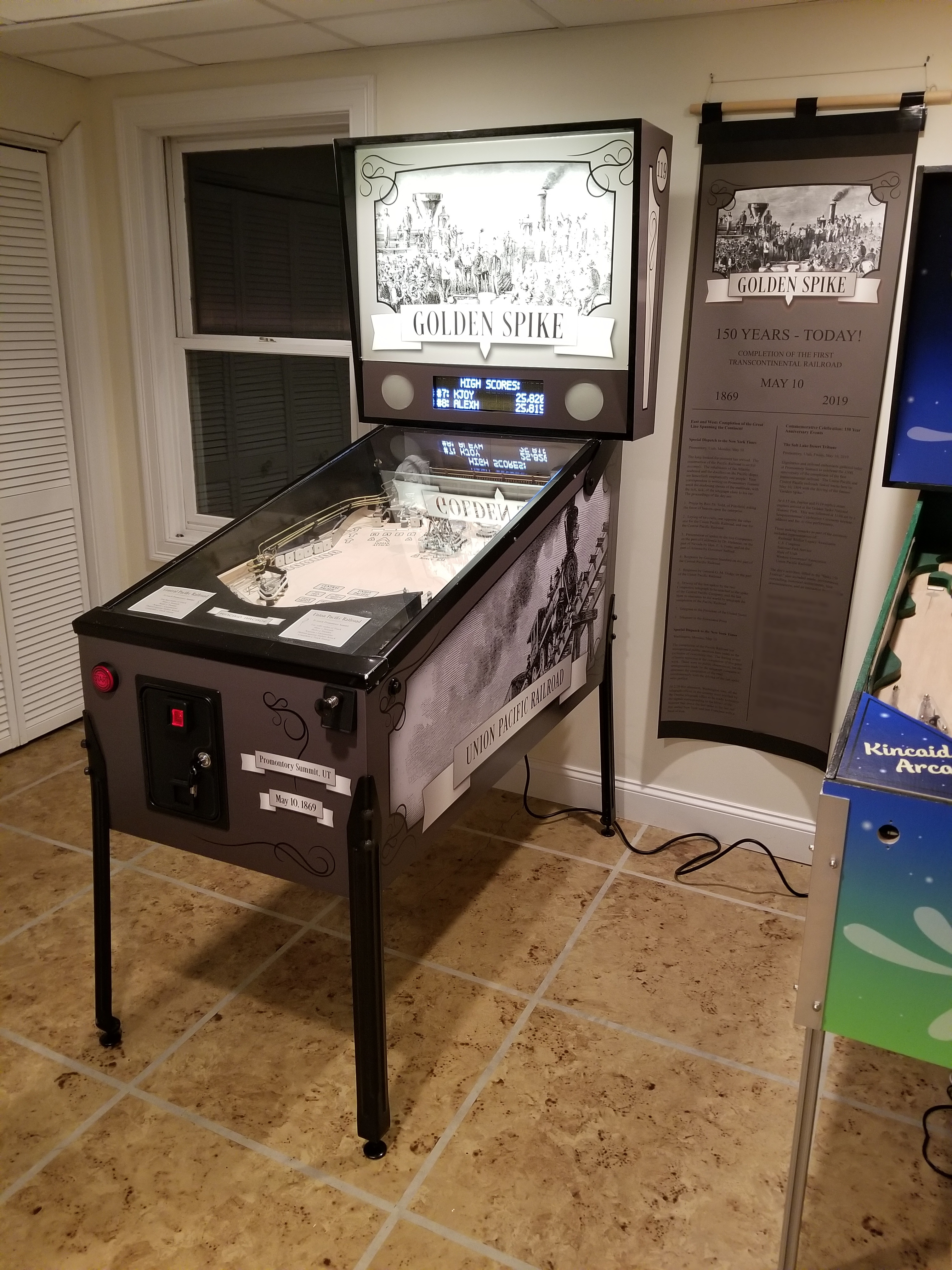
The Golden Spike Pinball Machine: 150th Anniversary Edition
How I responded to my Dad's father-son pinball build-off challenge.
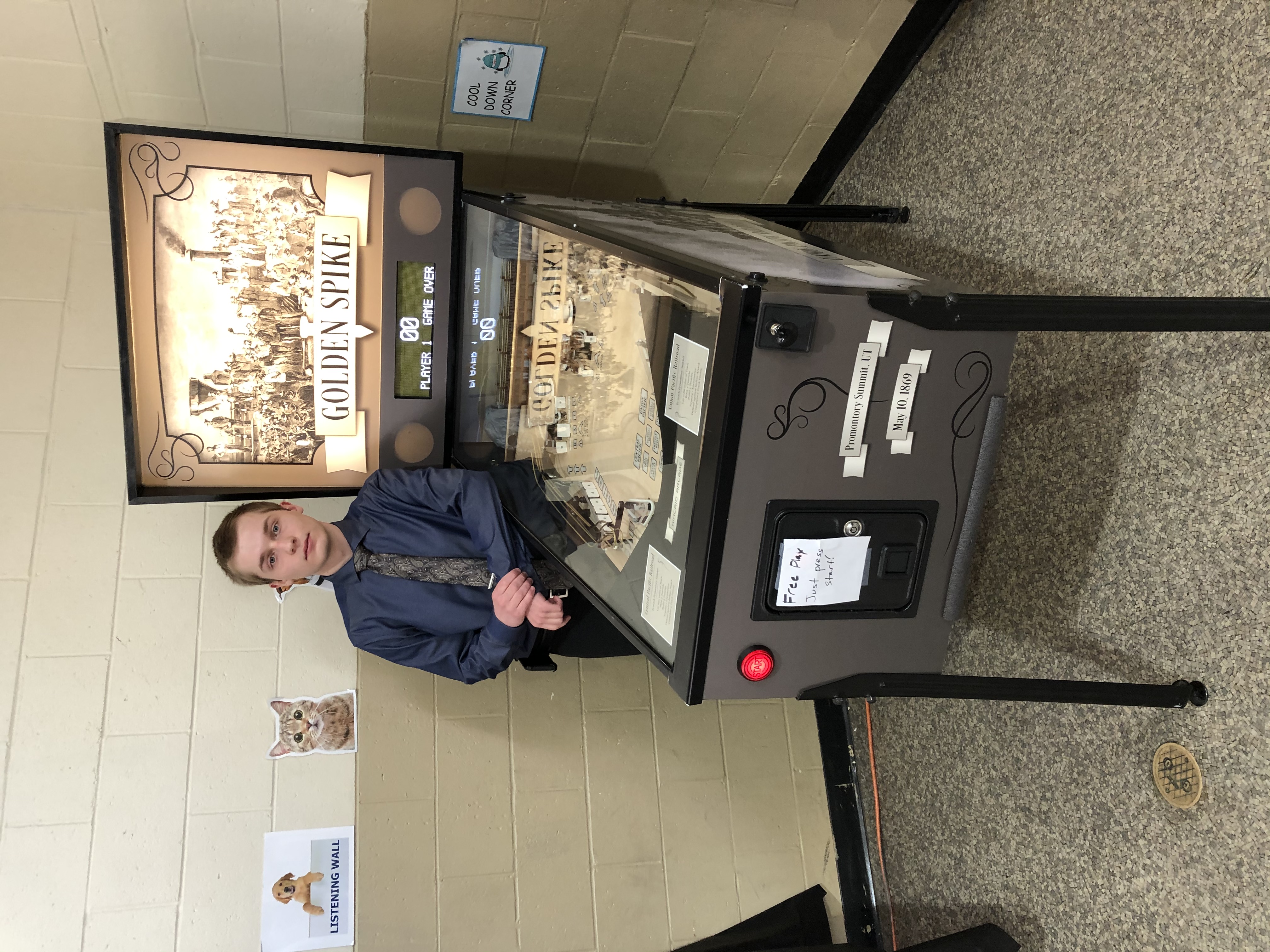
Finally finished, after 2½ years

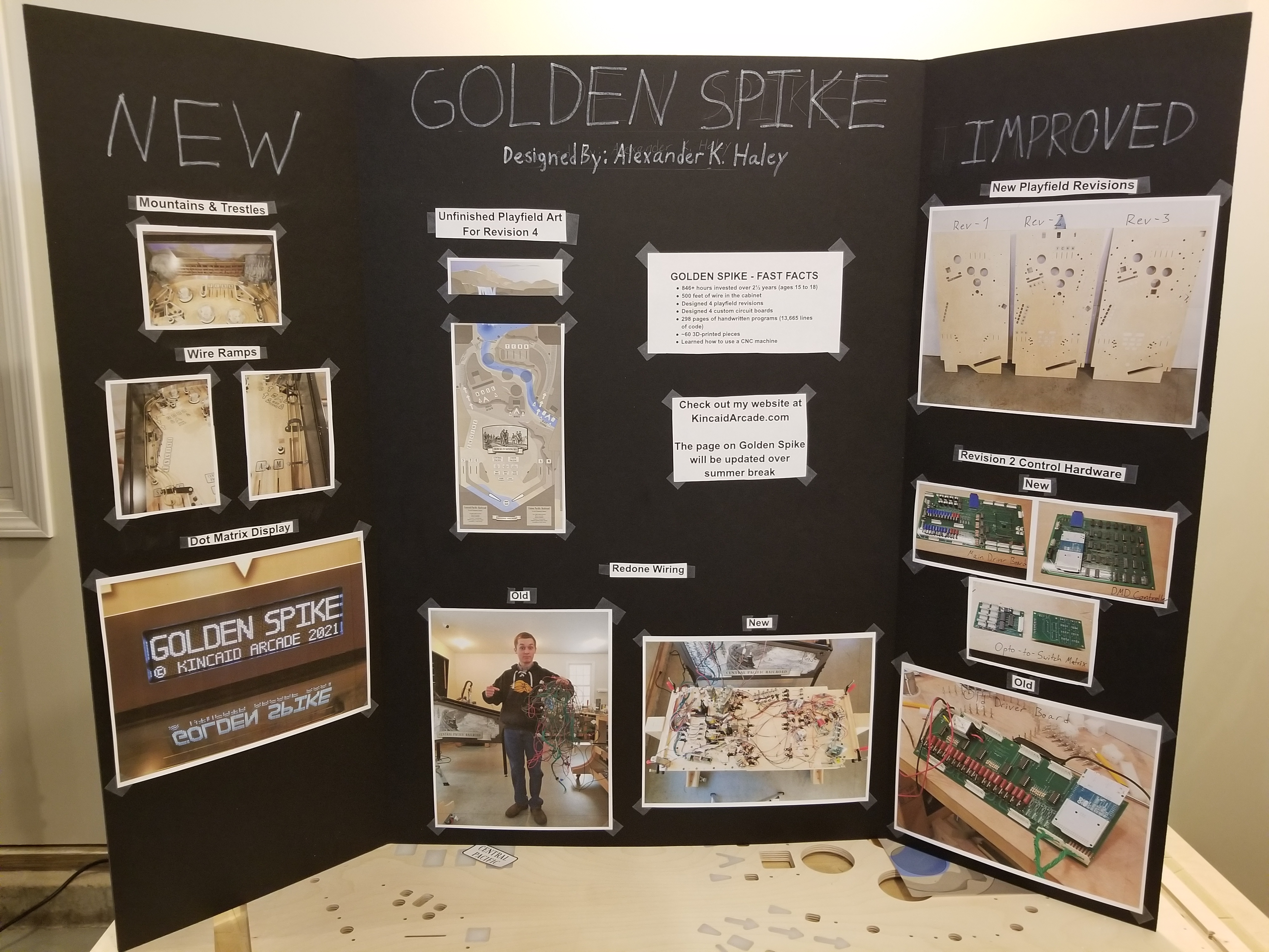
Golden Spike - Fast Facts
- 846+ hours invested over 2½ years
- 500+ feet of wire in the cabinet
- Designed 4 playfield revisions
- Designed 4 custom circuit boards
- 298 pages of handwritten programs (13,665 lines of code)
- More than 150 3d-printed pieces
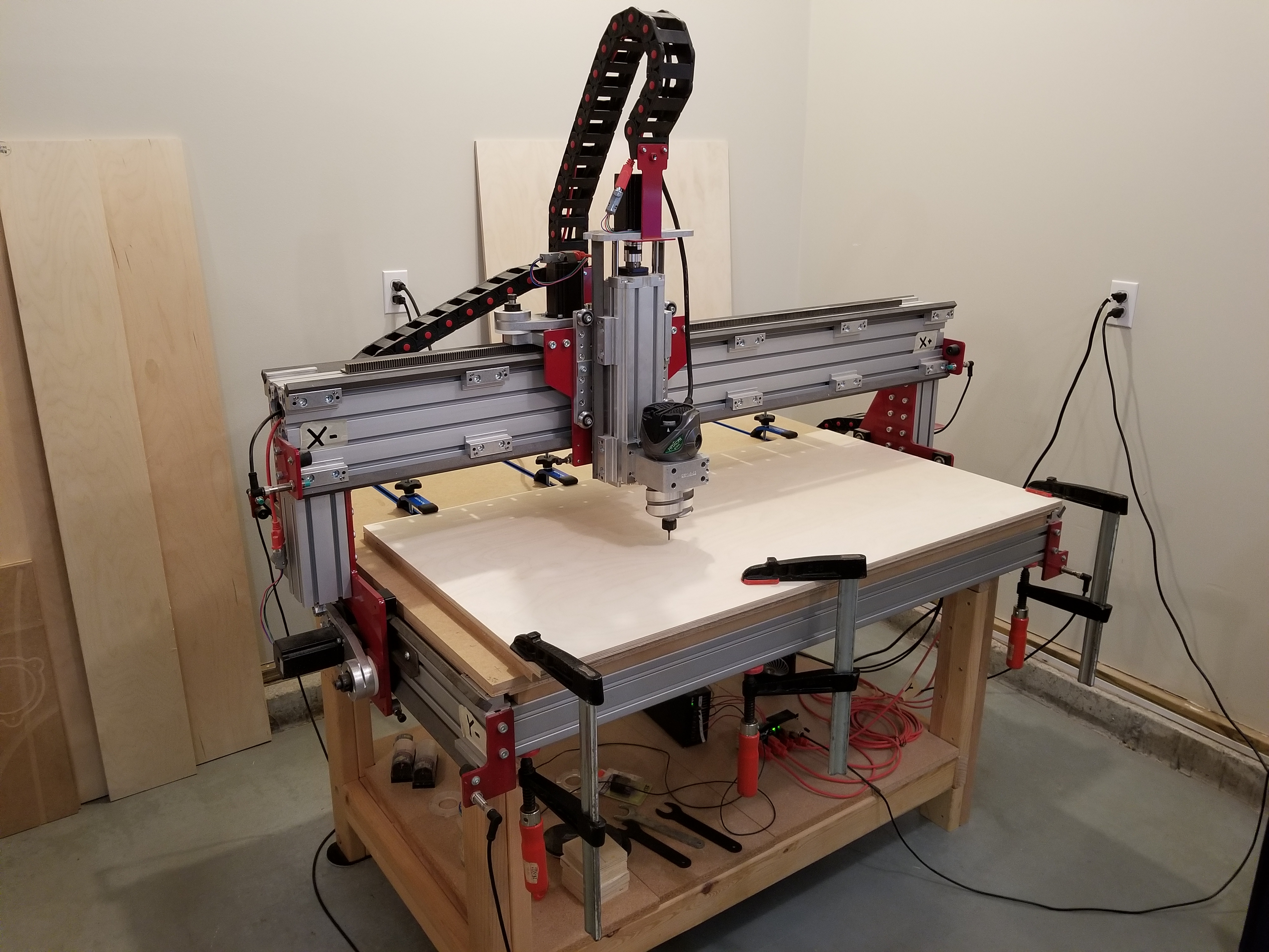
- Learned how to use a CNC machine
About Golden Spike
This pinball machine was my big project for the 2018-2019 schoolyear, although I continued working on it until it was finished in May of 2021. To date, I have logged a total of 846 hours over a span of 2½ years designing and bulding every aspect of it except for the artwork, which was done by my Dad.
I built both of my pinball machines with a slightly different purpose in mind than a normal hobbyist. The purpose was to have a singular, very impressive project that I can point to that demonstrates the many different skills within the realm of electronics that I have learned throughout the years. For example, this project involves loads of programming, 3d part design, 3d printing, CNC machining, circuit board design, and other forms of electrical design. This has been very useful when talking to people in the engineering department of the college I will be attending or when applying for scholarships.
As a result of learning many new things, this pinball machine has many improvements over Garden of Eden. To start, I designed my own control hardware from scratch instead of using the Power Driver 16 board. The new hardware consists of three boards: a control board, a DMD driver board, and an opto-to-switch-matrix board. The control board can drive up to 32 coils, read a 16 x 8 switch matrix, control 8 strips of addressable LEDs, and also save high scores to an SD card. The DMD driver board can draw an image to the DMD at 200 frames per second if each pixel is only on or off, or at about 66 frames per second if I need to use 8 shades of grayscale. Lastly, the opto-to-switch-matrix board allows me to connect optoelectric switches (such as in a trough or VuK) to the switch matrix and read them as if they were regular leaf switches.
Additionally, I made use of many custom-designed 3d printed parts to hold lights or act as playfield elements. I used a CNC machine to fabricate each of the playfield revisions instead of using a hand drill. I wrote all 298 pages of the game program by myself. I was able to add a lockdown bar and receiver, siderails, and playfield glass. I included molex connectors in every part of the wiring harness. And best of all, I finished it to my satisfaction (GoE was supposed to have a "walk with God" ramp).
How This Project Came About
This project came about as a challenge posed by my Dad after the completion of Garden Of Eden. (GoE for short) The challenge was such: I build a pinball machine, he builds a pinball machine. We have Mom judge between them, and whoever she names victor is the victor.
Now, let's be real here: having my Mom judge between a pinball machine made by her husband and one made by her son isn't a very fair thing to do to her. So, in late 2018 / early 2019, when this build-off was in progress, my Dad suggested we have some friends judge between them. Since his machine still has a long way to go (even in 2021) and I'm heading off to college, it likely won't be happening anytime soon.
How I Chose My Theme
I was originally planning on doing a pinball machine themed around ironclad warships. Unfortunately, that concept didn't make it very far.
So, I had to choose a new theme. After about a month of throwing out other themes, I couldn't come up with a theme that was beyond mediocre. Then, I suggested that I do something along the lines of the 'age of steam'. Not like steampunk, but things like mills and steamers and trains. My parents loved the idea, so it was full steam ahead. (Sorry, I had to make that pun.) After doing more and more research (because the first step is always research), I came to the conclusion that my pinball machine would have more to do with railroads than with anything else. What better way to do that then to focus on the nailing of the Golden Spike? And thus, Golden Spike was born.
As of right now, my machine is finished (except for PF-4, which needs artwork). My Dad's machine for our competition, at the time of writing, has gone through several playfield revisions but still needs loads of work. Our cabinets are slightly different; my machine is a widebody machine (the playfield is 46" long by 23.25" wide), and my Dad's machine is halfway between a standard and a widebody machine (his playfield will be 46" by ~22.25" wide).
Gameplay
As can be inferred from the name, Golden Spike is a pinball machine themed around the United States' First Transcontinental Railroad. In the game, you must complete shots in order to lay tracks, build trestles, blast tunnels, acquire locomotives, and defend against the occasional Indian attack on the railway line. All for 25¢ a game!
There are a total of three multiball modes in Golden Spike: the Track Frenzy multiball (2 ball), in which players must shoot the spinners or pop bumpers to lay 100 miles of track, the Indian Attack multiball (2 ball), in which players must spell I-N-D-I-A-N-S to protect the track crews, and the Railroad Completed multiball (3 ball), which is awarded upon shooting the supply tower VuK once all goals required to build one of the two railroads are completed.
Tracks are built with each hit to the pop bumpers, spinners, and slingshots. Tunnels can be blasted by shooting the tunnel VuK on the right side of the playfield. The point bonus given upon completion of the tunnel is dependent on whether or not the adjacent nitroglycerine targets were hit. Trestles can be built by shooting the "A" of the INDIANS targets, which opens a diverter that diverts shots up the right lane to the trestle VuK that is hidden in the 3d-printed mountains. The kicker then fires the ball up and over the trestle, and then rolls down the left wire ramp to the "T" return lane. Locomotives can be acquired by spelling ENGINE with the targets on the left of the playfield.
Shooting the supply tower kicker gives a random reward if no other modes are active. If a reward has never been recieved, it starts the track frenzy multiball. Otherwise, it will either award 1,000 points, 30 miles of track, a trestle, tunnel, or locomotive, a track frenzy multiball, or rarest of all, an extra ball. The supply tower is guaranteed to award an extra ball every time the player's score passes a multiple of 30,000.
At the end of each ball, there is an end-of-ball bonus. Points are awarded for the number of miles of track laid, trestles built, tunnels blasted, successfully completed track frenzies, repelled Indian attacks, and locomotives acquired. The machine also tells you what point along the route (depending on which railroad you selected) the tracks have reached, based on the miles of track you laid. At the end of the game, the match can be set to award a free game or an extra ball (because getting a free game when you own the machine isn't very fun.)
Building It
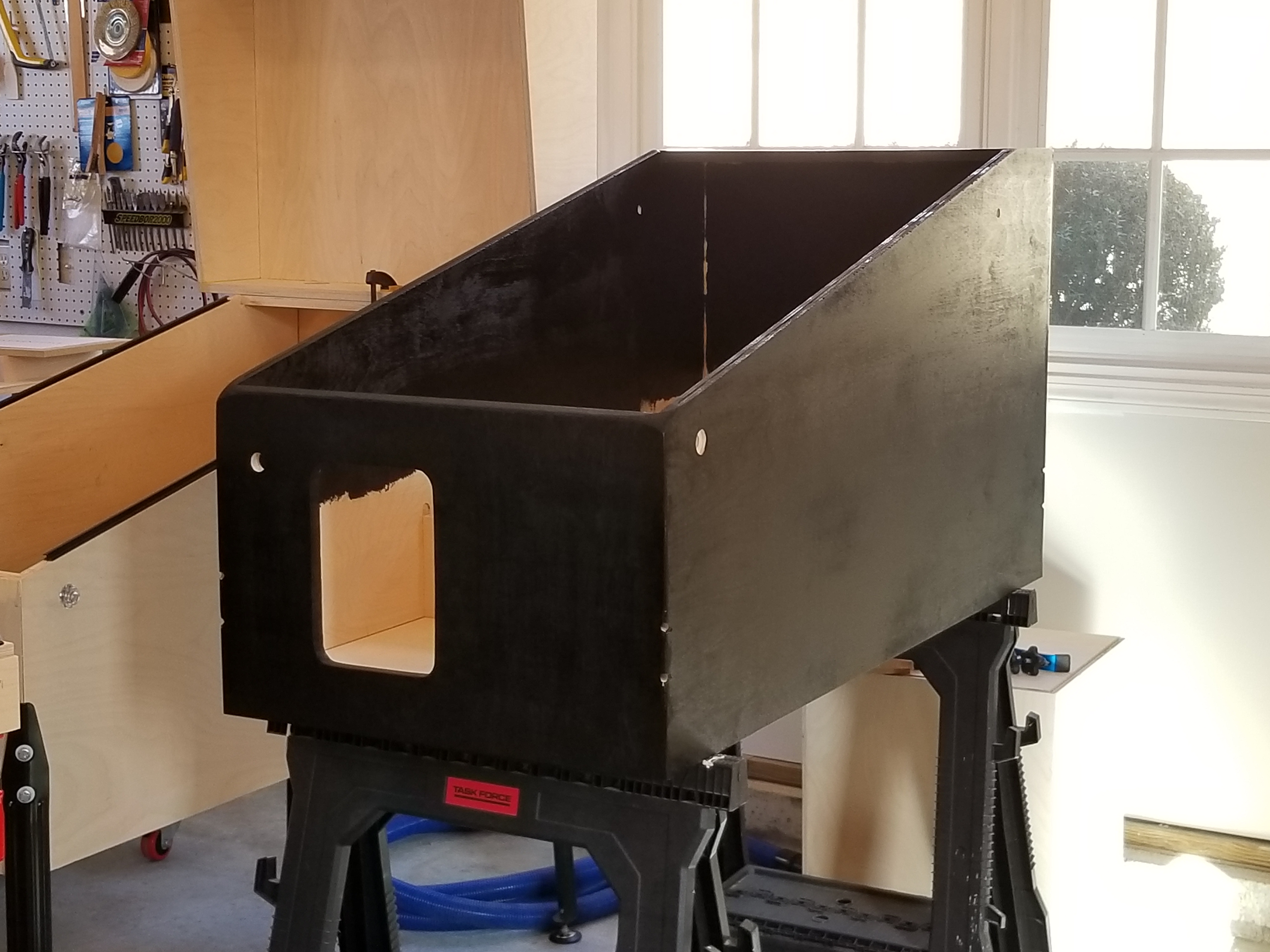
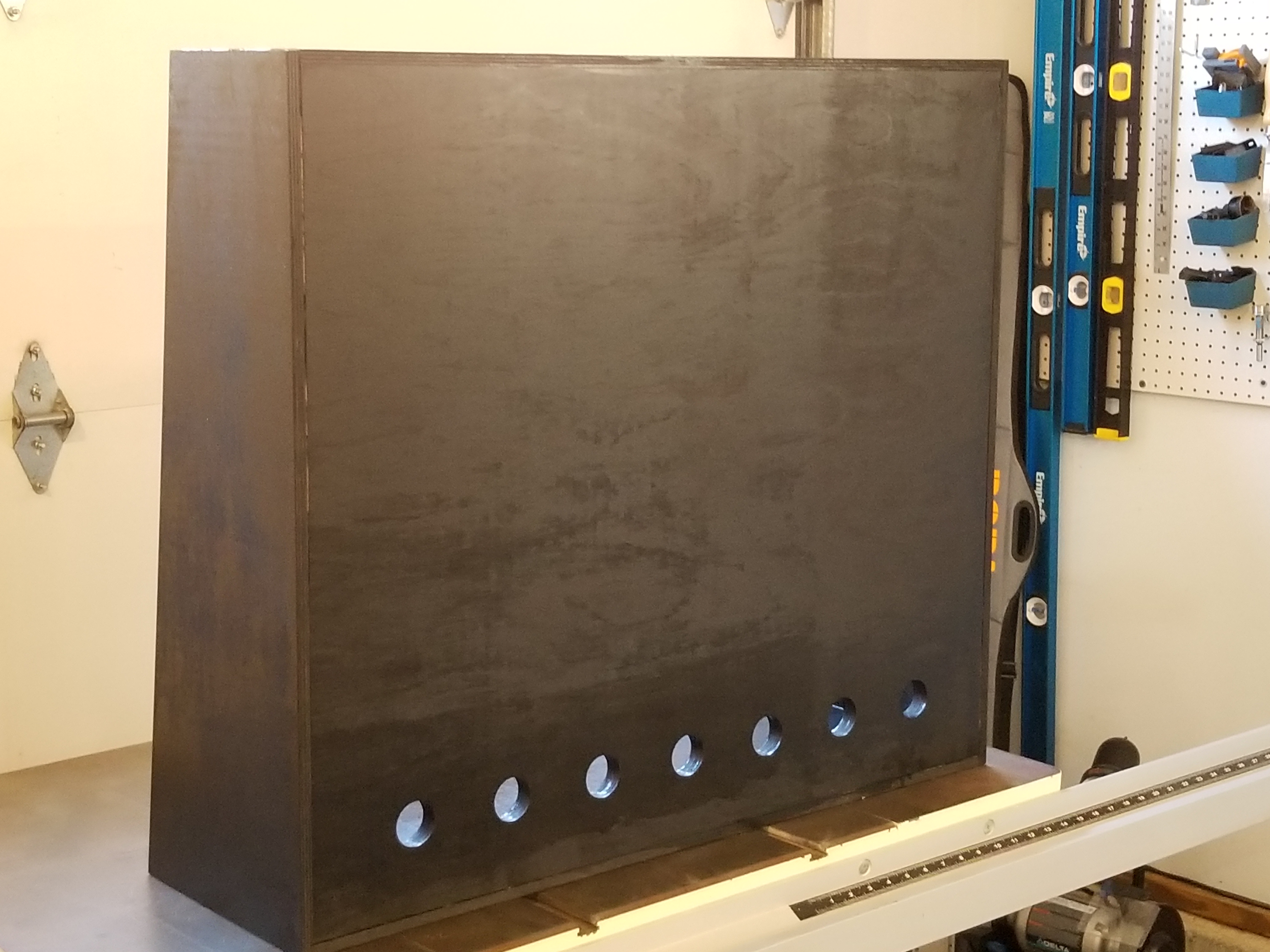
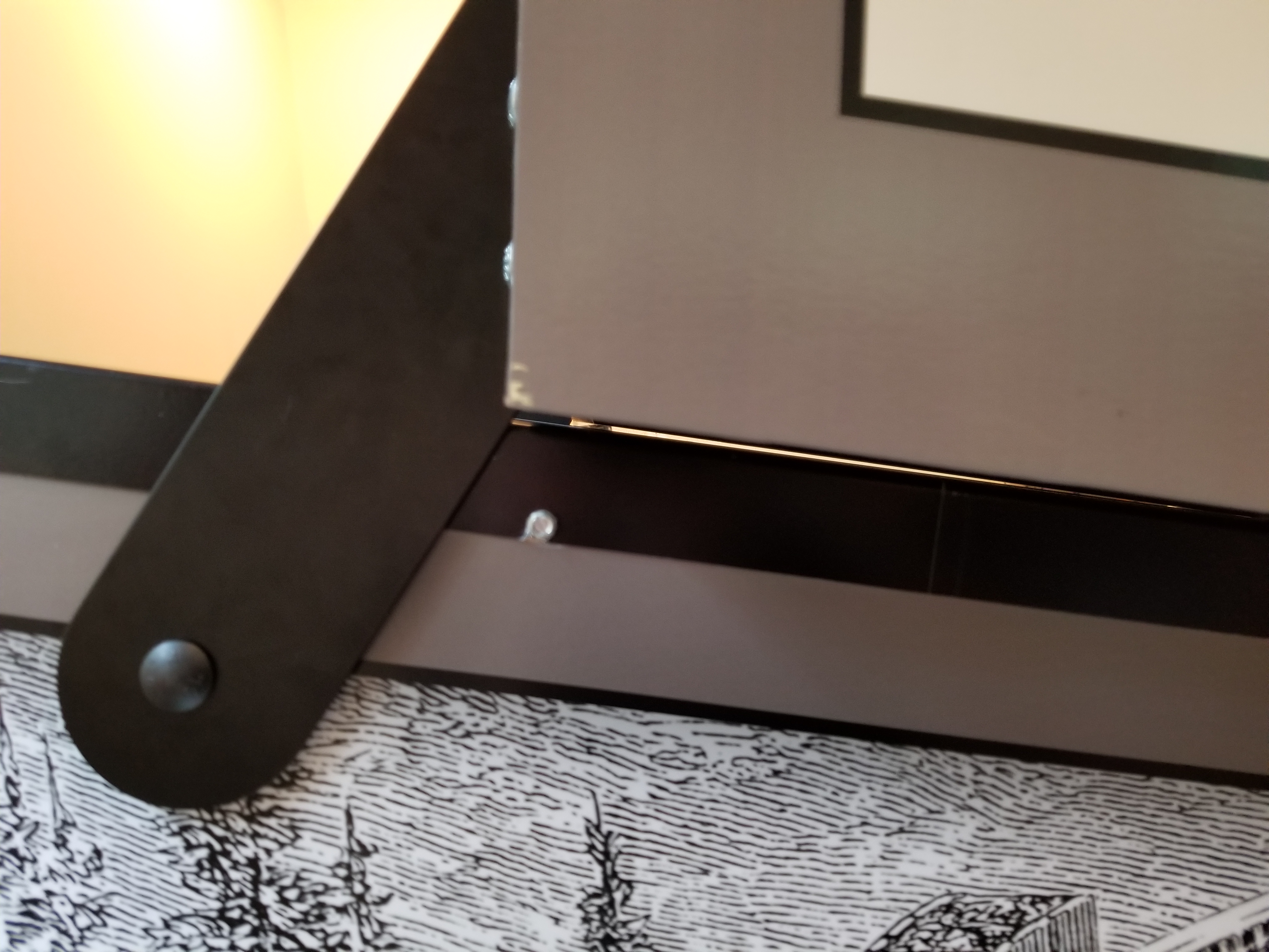
The very first thing we did in building our pinball machines was design and build the cabinets. Standard pinball cabinets were tilted slightly through the use of their legs, allowing for a smaller cabinet to be used (in the vertical dimension of the playfield box). They did this by mounting the playfield at something like 3 degrees within the cabinet, and then offsetting the front and back legs to produce the other 3 - 3.5 degrees. My Dad and I didn't like that; we thought it felt like laziness on the part of the designer and manufacturer. We chose not to go this route, instead we made our cabinets to have a playfield that is already at 6.5 degrees, with a bottom that is always parallel to the ground. This design choice made the bottom portion of the cabinets look slightly different than normal, but we were quite pleased with the results in the end.

The bottom box to one of our cabinets.
Using what we had learned from the Garden of Eden, we made a change to how we glued up the cabinet. We used some belt clamps to apply force evenly around the cabinet. We were quite pleased with the results.

My cabinet gluing. You can see my Dad in the background.
Before we glued up my cabinet, my Dad walked me through how to design things for the CNC machine to rout out. Some of the first programs I ran over our CNC machine were of simple things: flipper button holes, speaker holes, coin door holes, etc. Unfortunately, I didn't quite get the dimensions right, so I had to do a lot of sanding on the coin door hole.
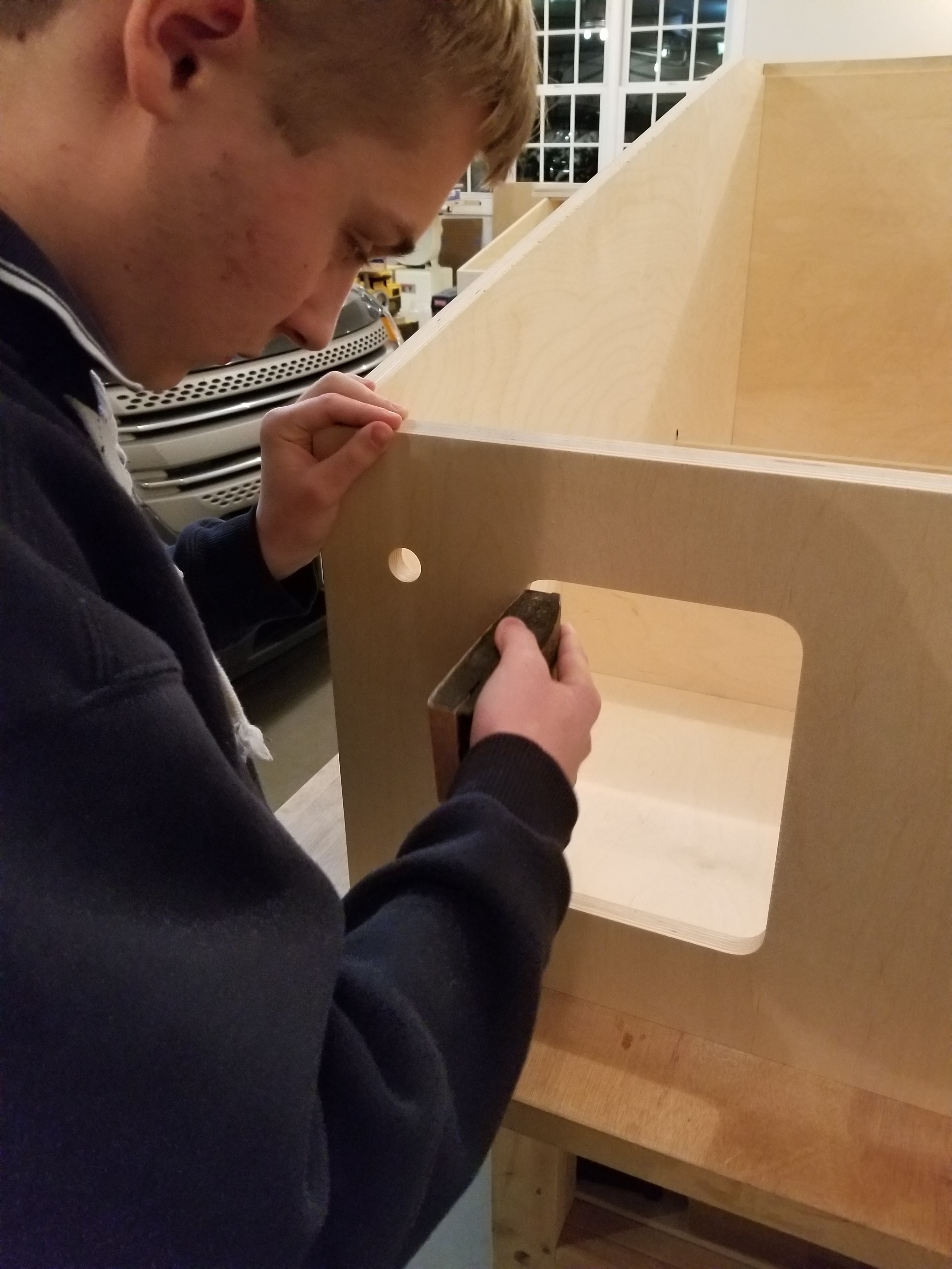
As you can probably imagine, I was there for several hours...
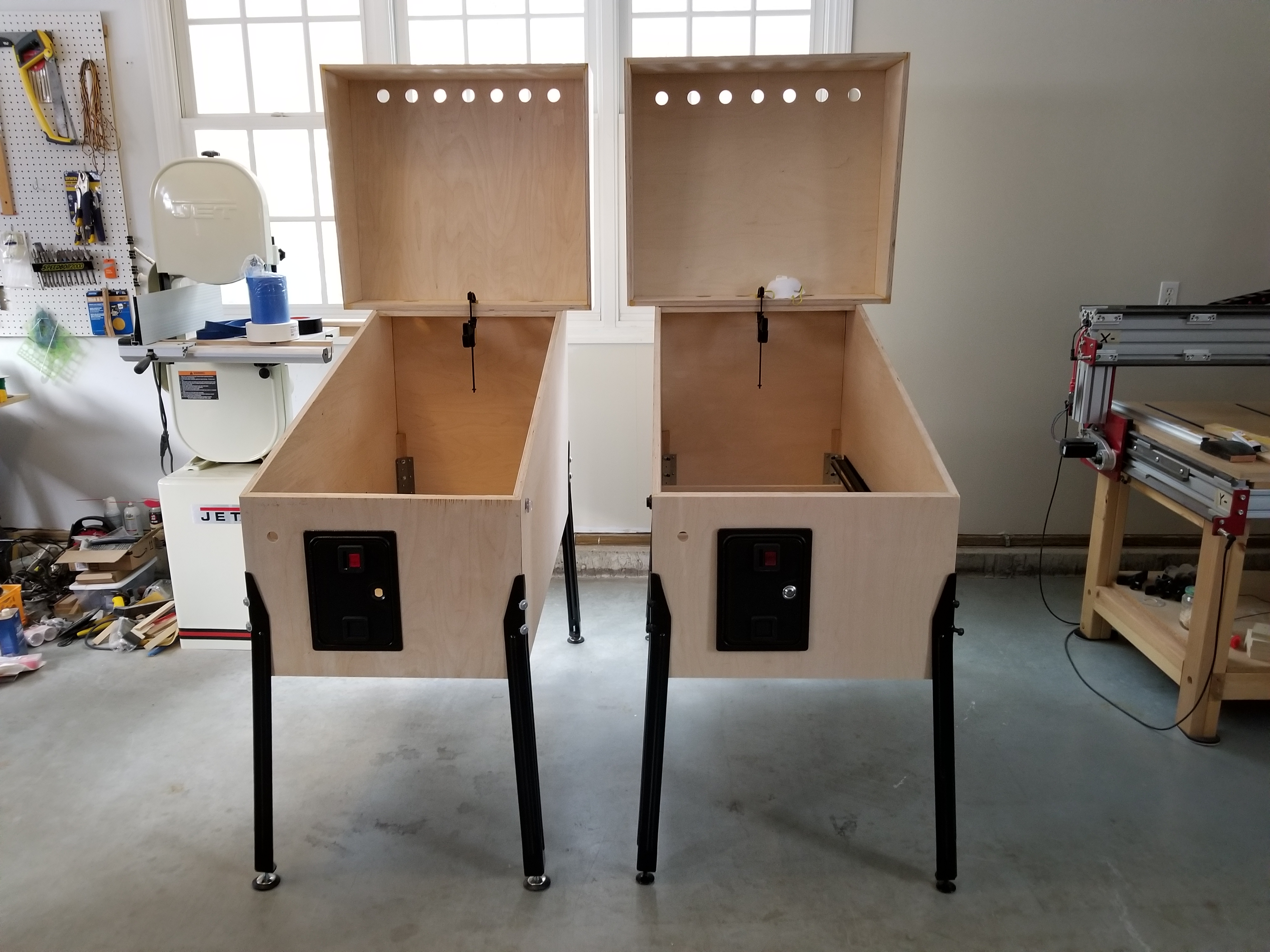
The cabinets without paint or art. My cabinet is on the right.
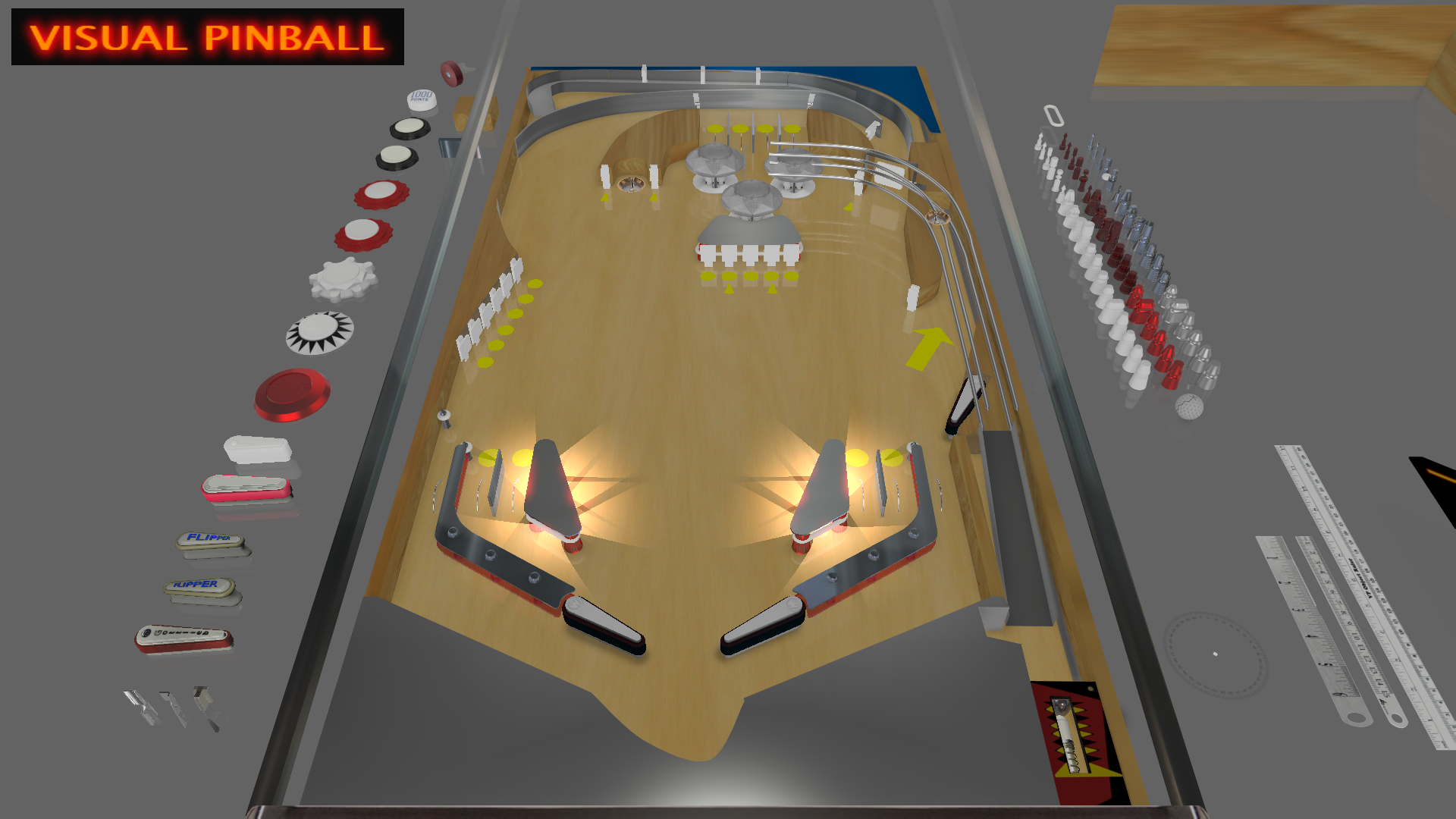
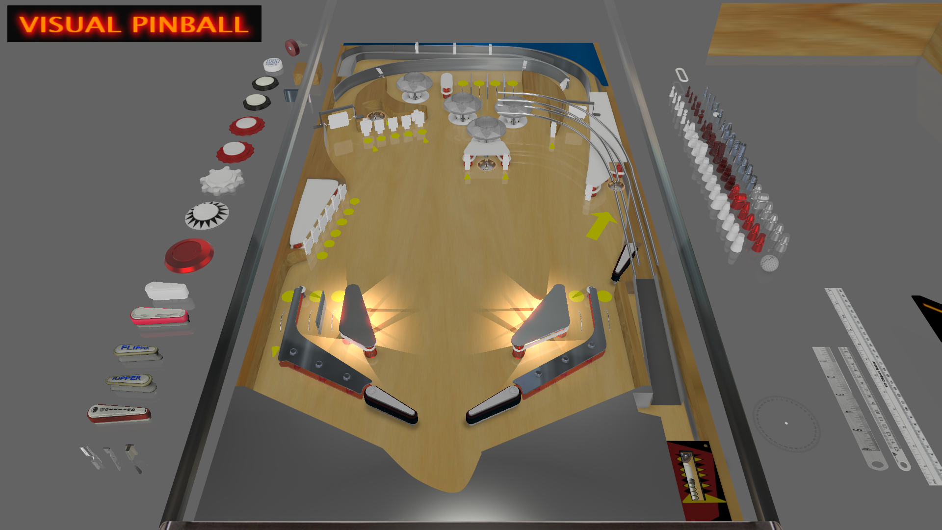
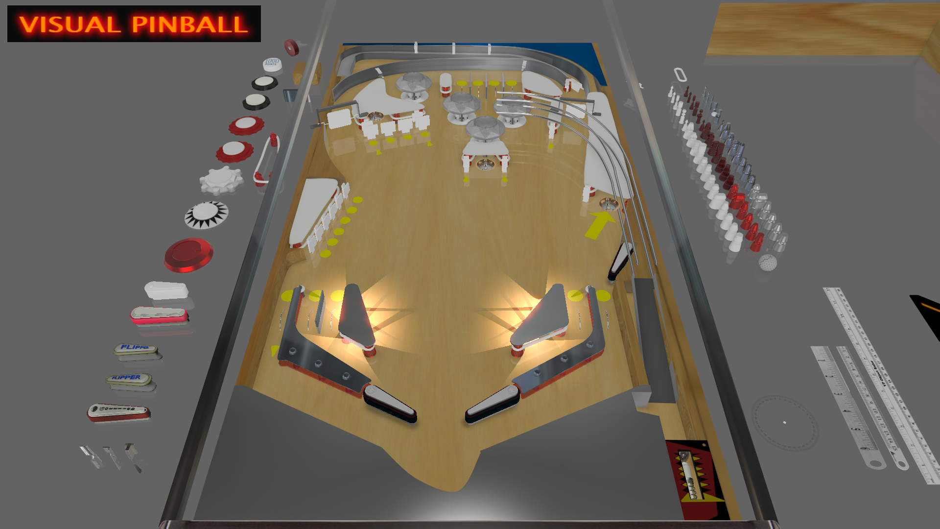
After building the cabinets, I had to figure out what I wanted the playfield to look like. In order to do this, I had to do a lot of research about the United States' first Transcontinental Railroad. After taking many notes, I began to write down what modes I wanted the game to have. I then began to lay out parts in Visual Pinball. After many hours of designing the game in Visual pinball, I finally had a layout that I liked. You can see several of my Visual Pinball layout revisions below.
After deciding that the layout was "finished", I got the approval of my Dad, and I started drawing it up in RHINO 6. (Amazing piece of software.) I drew up the footprints of the actual parts in Rhino. Not just holes, but the stuff underneath too. I did this because at the time I wasn't sure if I was going to use 3/4" or 1/2" wood for the playfield. If I used 3/4" wood, I would've needed to flip the playfield over and machine divets in the wood for the bottom pieces of the parts to rest on, because pinball parts were designed for 1/2" thick playfields.
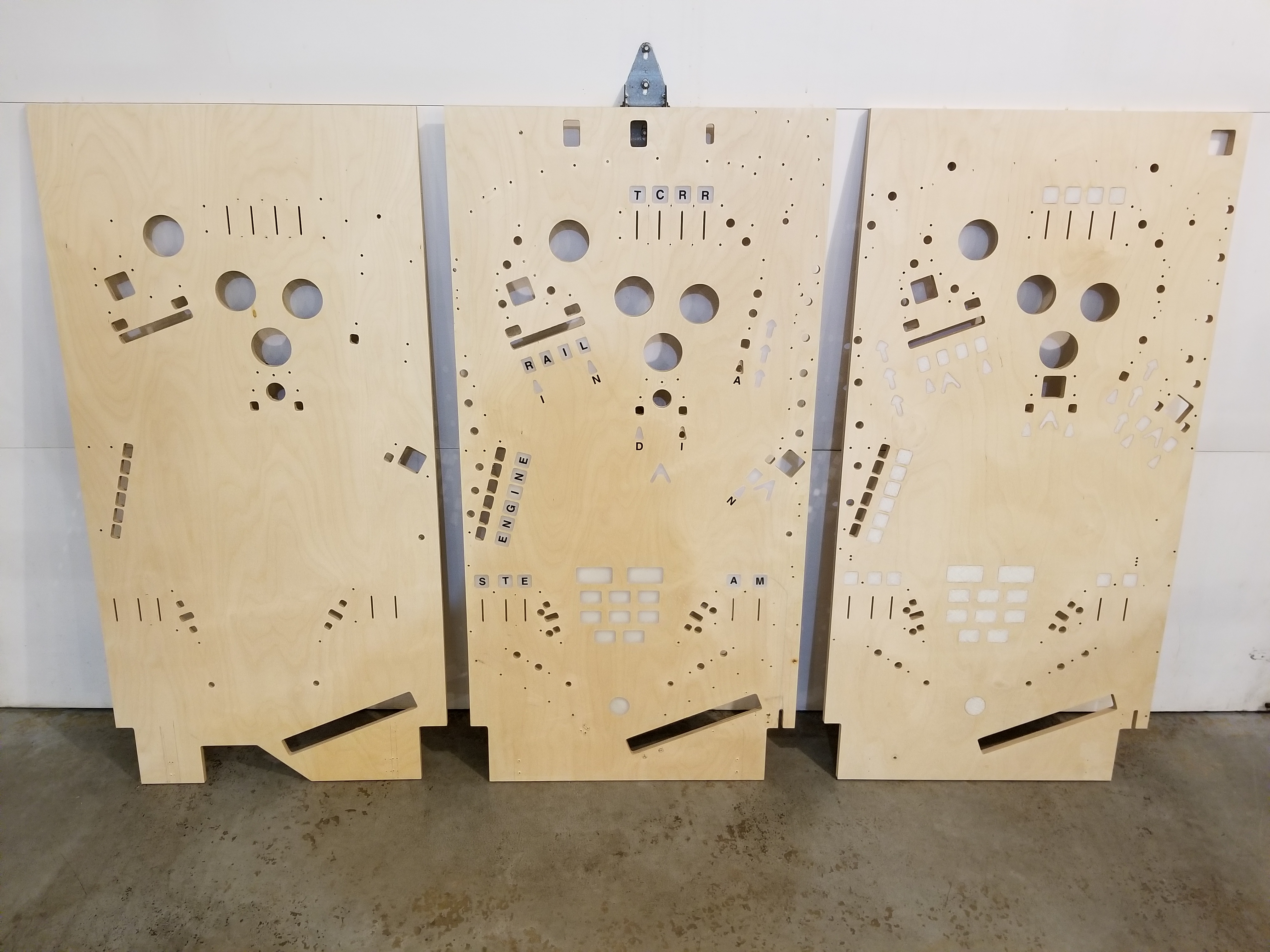
When I had to transfer the locations of parts from Visual Pinball to Rhino, things became tedious. Visual Pinball has a weird system of units: 50 VP units = 1.0625". For the next several days, I used many sheets of paper and my TI-84+ to convert VP units to inches. Things were really bad when I had to figure out the pegs... Eventually, it got done. Here are pictures of the Rhino file for each of the playfield revisions:

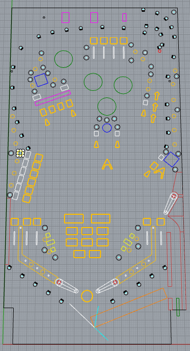
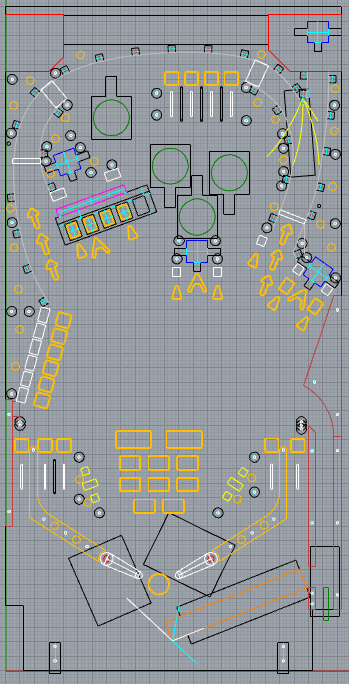
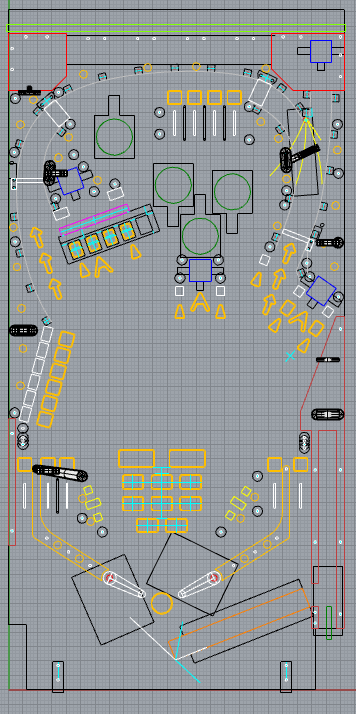
Left to right: Revision 1, 2, 3, 4
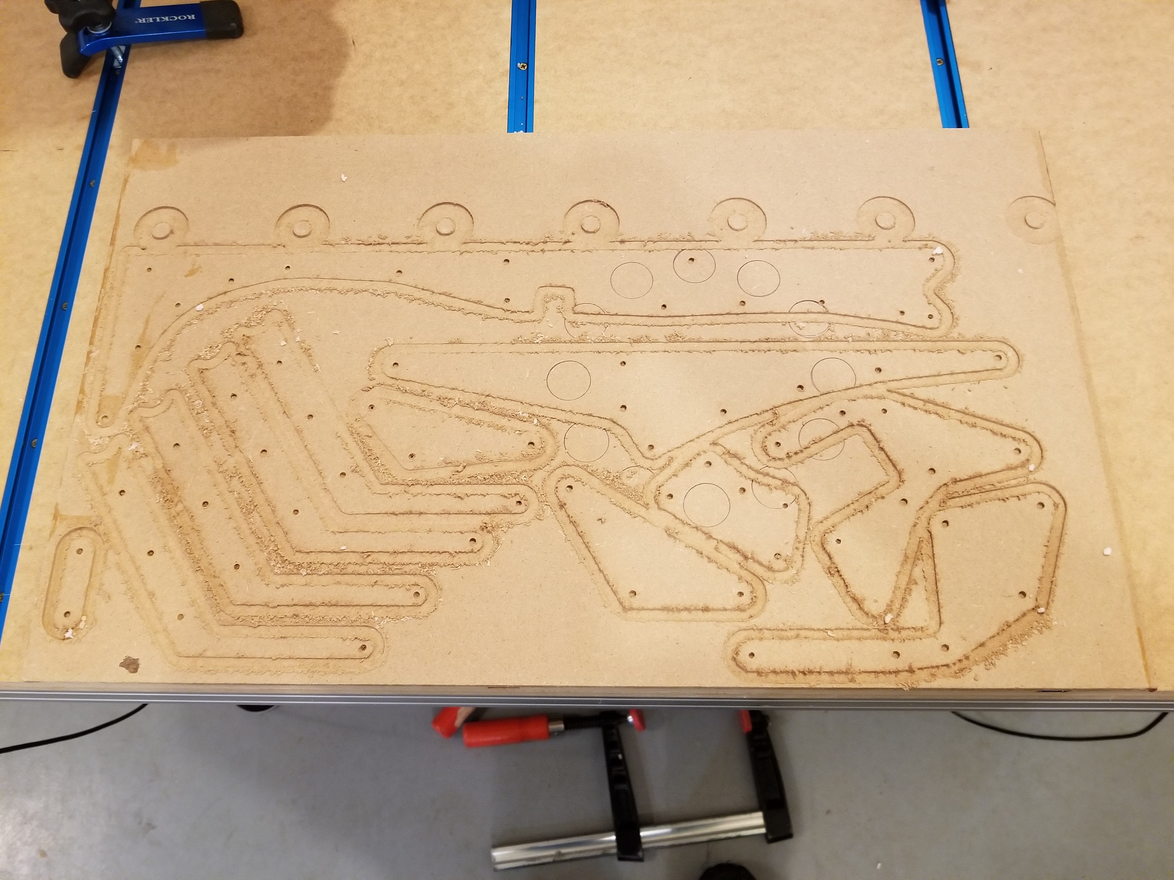
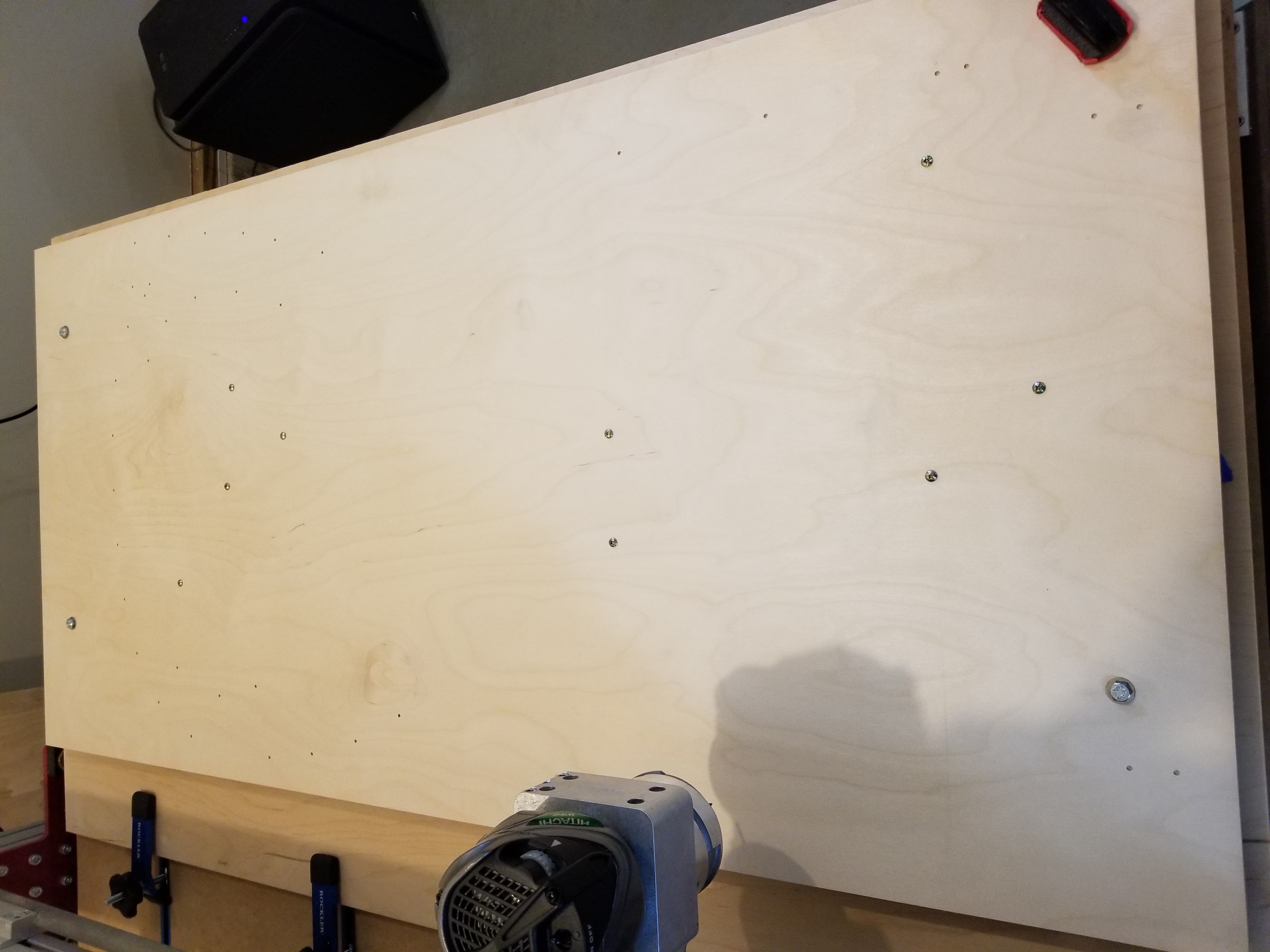
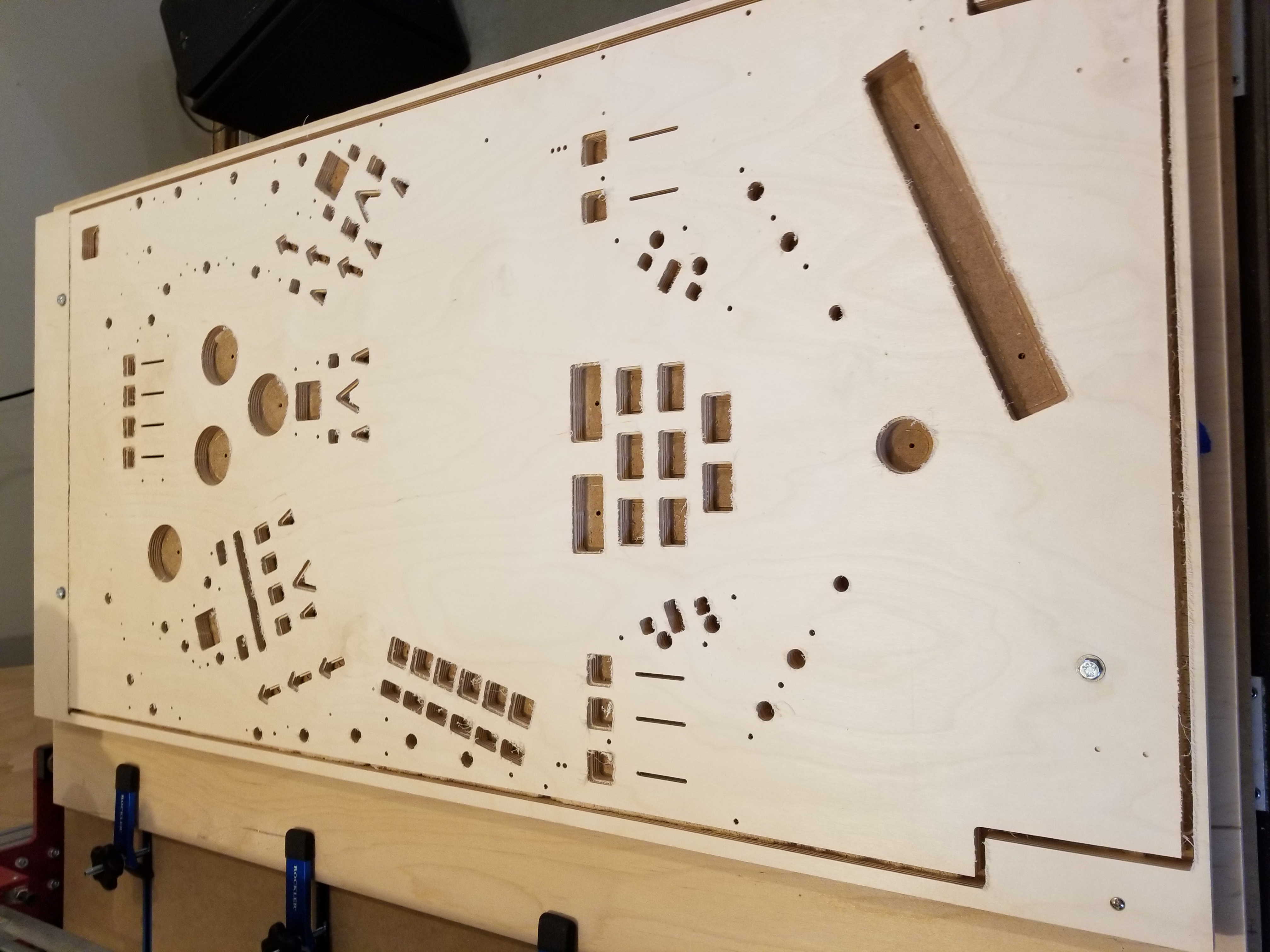
Even though the above photos represent a crazy amount of work, the Rhino files are still quite different from a physical playfield. Fortunately, with the help of a CNC machine, that can be changed. For each of the playfields, I had to spend several hours converting the Rhino file into G-Code for the CNC machine. After, it was a matter of holding the shopvac for several hours while the CNC machine cut out the playfield. The results were clearly worth the aches endured.
The first revision playfield! (Before being cut)
After being cut. That piece is about as large as the machine can handle, so we had to move the clamps a lot.
After cutting out the playfield and sanding the edges, I had to populate it with parts. That took awhile. Fortunately, my Dad designed and built some nice playfield rotisseries so it wasn't that difficult. They even had convenient trays to put parts!
It took the better part of a week to finish populating it, even though it was just a proof-of-concept whitewood. After I populated it with parts, it became pretty obvious that I wasn't going to be testing it any time soon due to the sheer number of changes I needed to make. Considering how long it took to wire up playfield #2, I'm glad I didn't. I also didn't have my custom driver PCB finished yet.
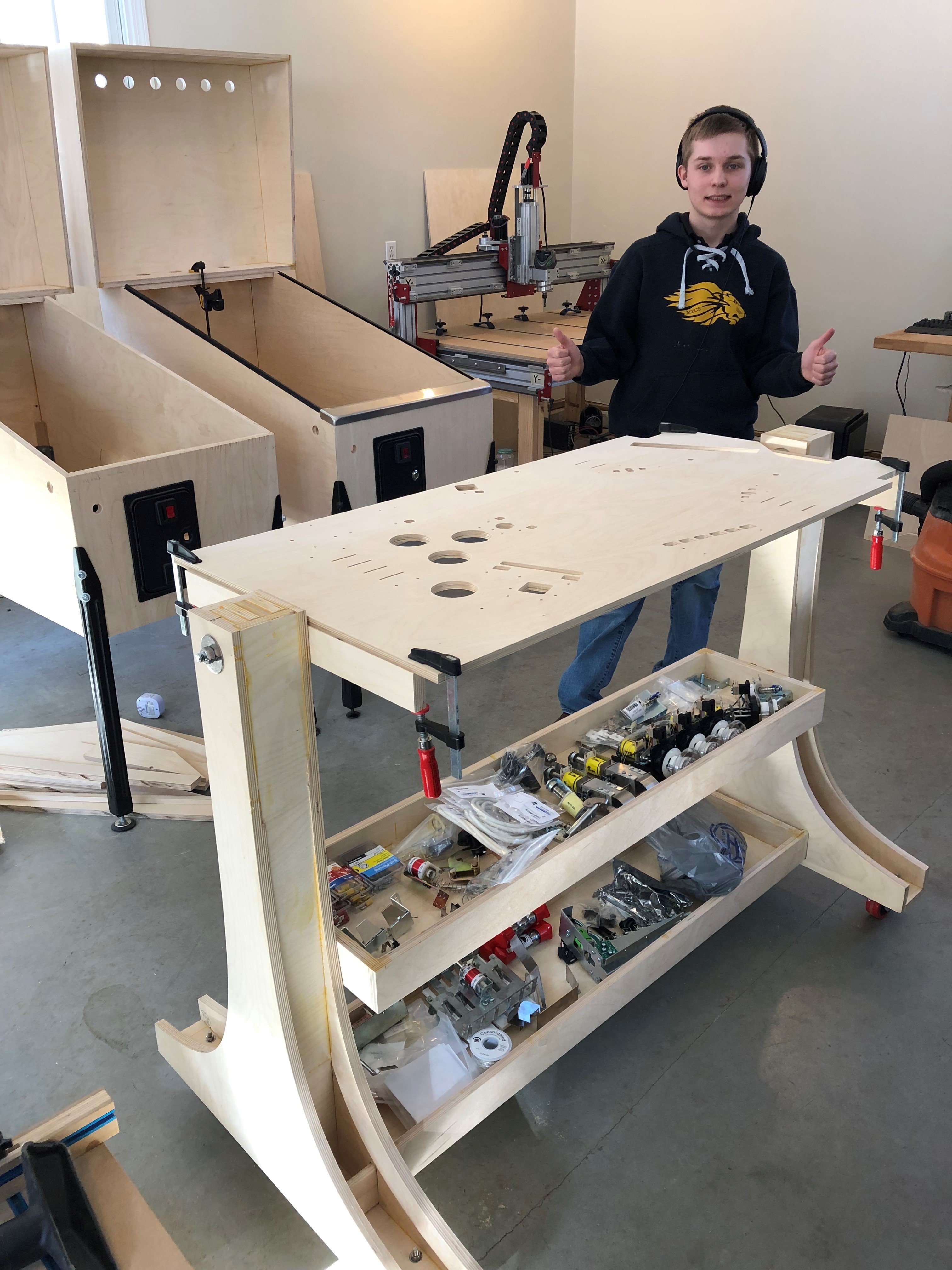
As you can see, I'm ready to be doing this for awhile. I think I was listening to Owl City.

The REV-1 playfield with parts.

The bottom of the playfield. Even though I only needed 4 drop targets,
I used a 5-bank of drop targets because they are cheaper than a 4-bank.
I remember my Dad and I getting into a mock argument after I finished populating this playfield. We had gotten strong and weak flipper coils, and I took the strong coils, leaving him the weak ones. He wanted the strong coils, but I had them, so he was a little jealous. Later, we discovered that the coils were a *little* too strong when driven by 48 volts. The ball would go flying any time it hit a target. Now, neither of us want the strong coils. Golden Spike currently has the weak flipper coils.
Between designing playfield revisions 1 and 2, I finished my driver board design. I spent a long time burning up TIP102s without having a clue why. I think it might be because I didn't fully understand transistors and driving a current-driven device (such as a transistor) with a TTL chip (~20ma output) wasn't the best idea. In the end, I opted for some IRL540s, and those worked just fine. I had Quickturnpcb fabricate my boards for me, and I was quite pleased with the results:
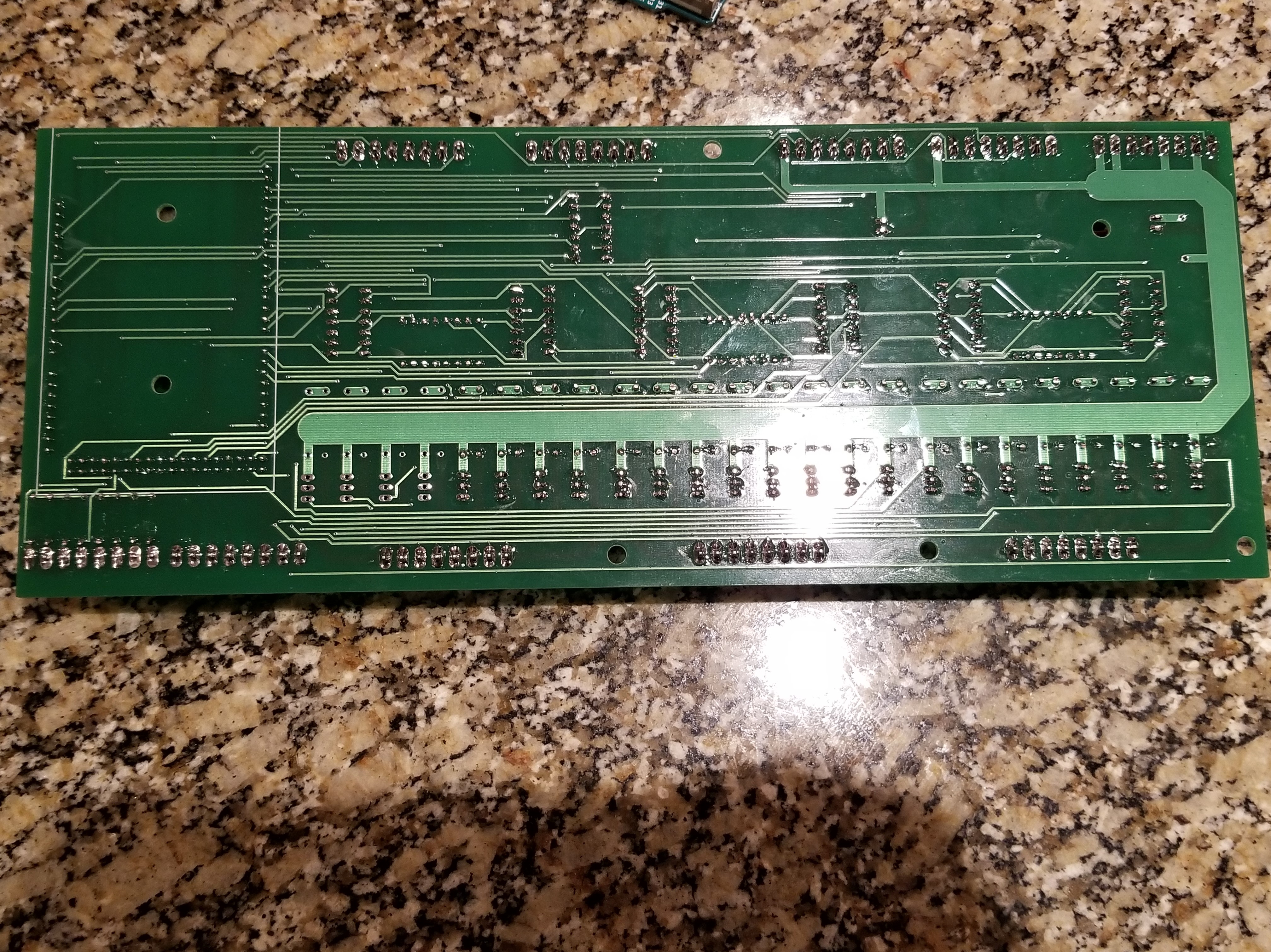
Aside from accidentally putting a molex connector a little too close to a bank of resistors, there was nothing wrong with the PCB I designed. As you will see later, I designed a second set of control hardware PCBs that are much more powerful.
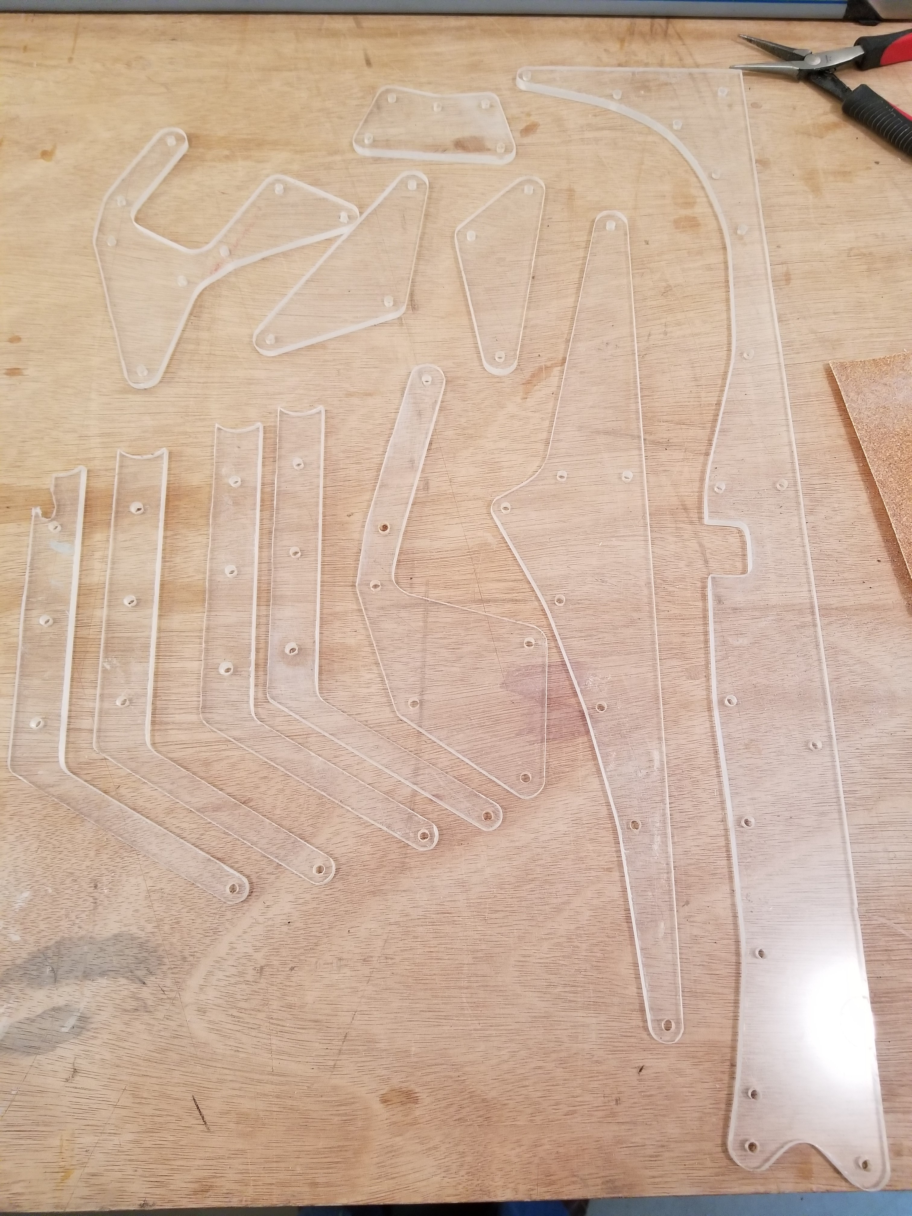
After soldering up the driver board, I began the long process of fabricating playfield prototype #2. I made sure to include all the walls and other stuff that would be required in order to make it playable/testable. I also added holes for the lighted inserts. My inserts aren't standard inserts; I designed and 3D printed my own inserts with translucent filament for each of the playfield revisions.
I had a pretty respectable pain in my back after
holding the vacuum for several hours.
Before I started populating the second playfield, I painted the cabinet. I did, after all, have to get the cabinet ready to recieve a playfield for testing! This provided a solid background for the vinyl sideart to be applied to.
After doing that, I simply had to put one foot in front of the other in order to finish populating the second playfield. It took much longer than the first playfield. I had lots of parts in odd places, which made the order of assembly a little bit difficult. Sometimes it was even frustrating, especially when I had to remove the drop target bank to put some spot targets in behind/beneath it.

A side-by-side comparision of the REV-2 and REV-1 playfields.
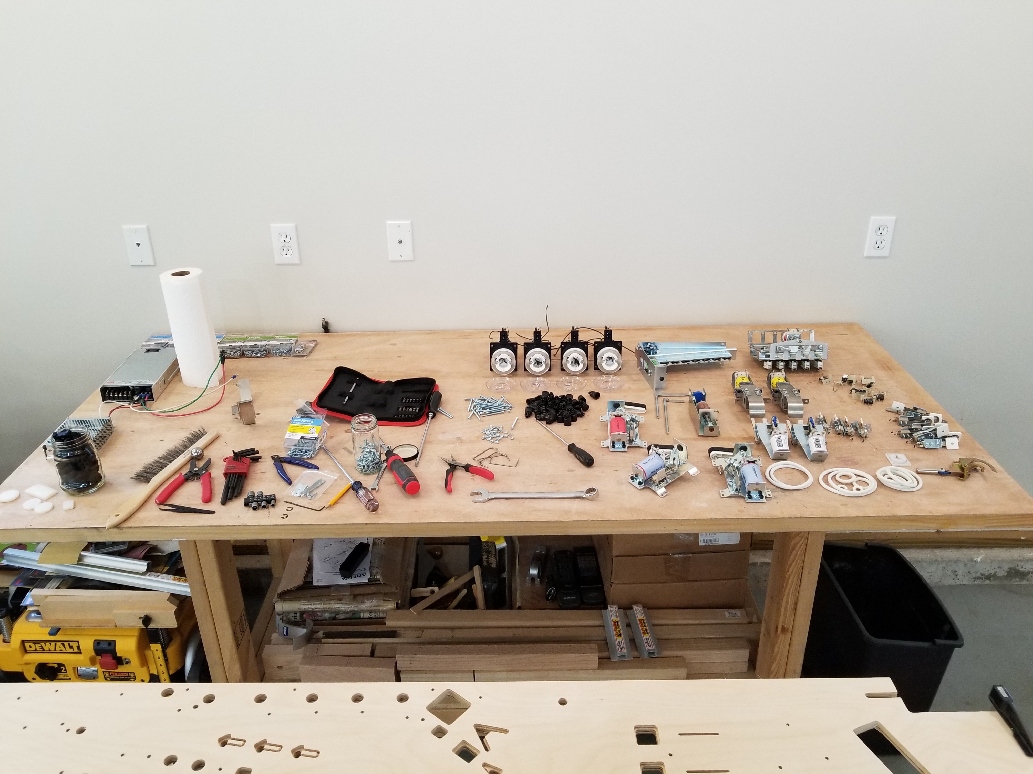
Some of the many physical parts that go onto a pinball playfield.
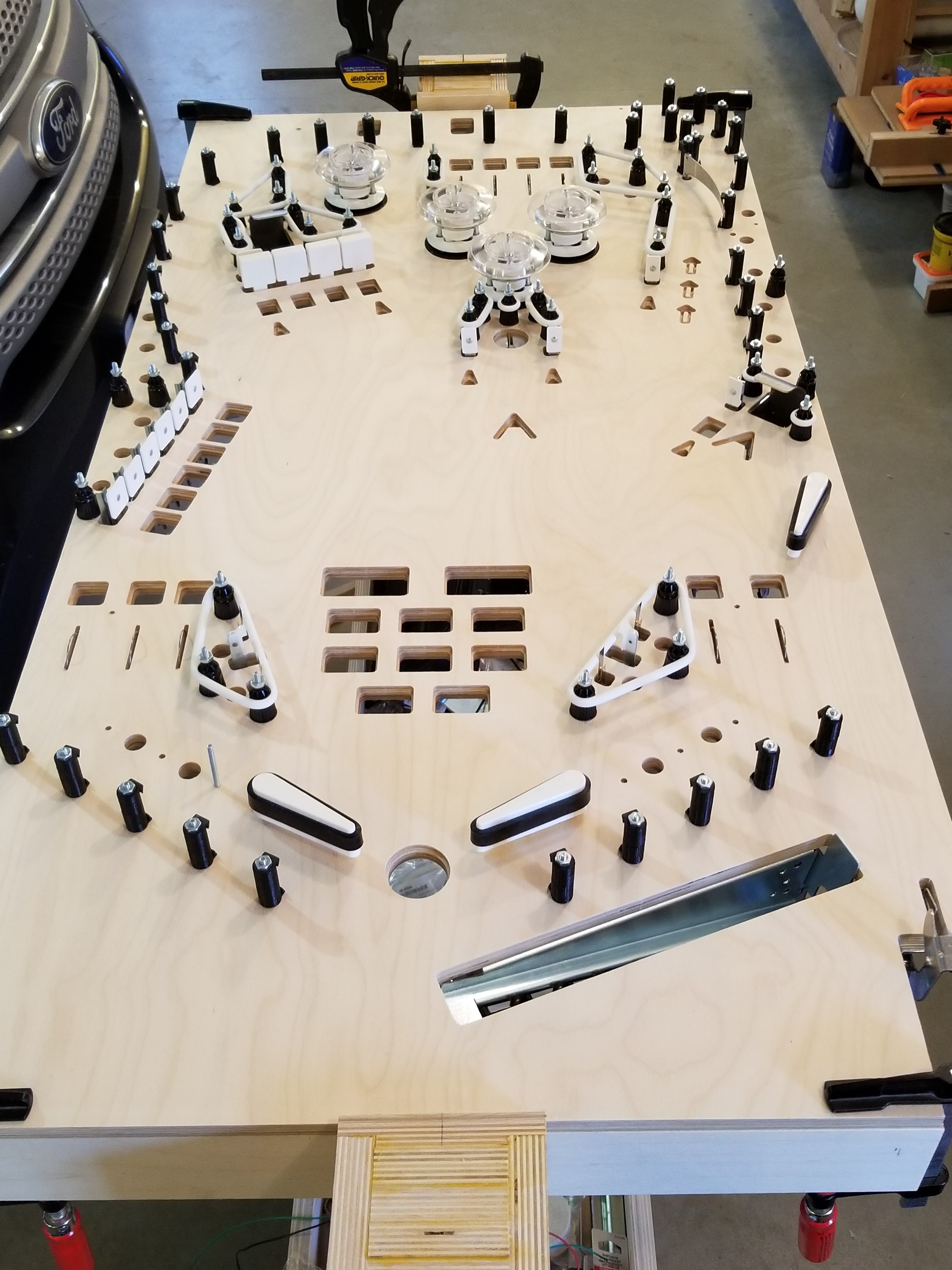
The top of the playfield after mounting almost everything.
After populating the playfield, I had to wire it up. I started with the switch matrix, then I did the coils, and I ended with the addressable LEDs. At each stage of the process, I had to write code to test what I had wired up. I wanted to make sure all of the issues with the playfield wiring were ironed out before I put it into the cabinet. In the case of the switch matrix, there were only one or two wires and a couple of diodes that were in the wrong place. The test program that I wrote made it pretty easy to see which rows and columns had problems. Even something as simple as putting a diode in the wrong direction will make a column of switches look like they are pressed.

The wires of the switch matrix columns.
I had to solder a lot of diodes onto the switches.
This picture was taken before I put in the weak flipper coils.

The setup I used for testing the switches.
I paused after testing the switch matrix to finish up adding the appropriate cabinet hardware for mounting in the playfield. I had to put in brackets to support the playfield, and I also had to drill the holes for the shooter mount. In both of the pinball machines I've built, mounting the shooter has been a very tedious task.

Putting in playfield mounts.

Test fitting the first playfield.

Me drilling holes for the shooter.
The unpopulated REV-1 was used to see if the mounting hardware was in right. All the angles were correct.
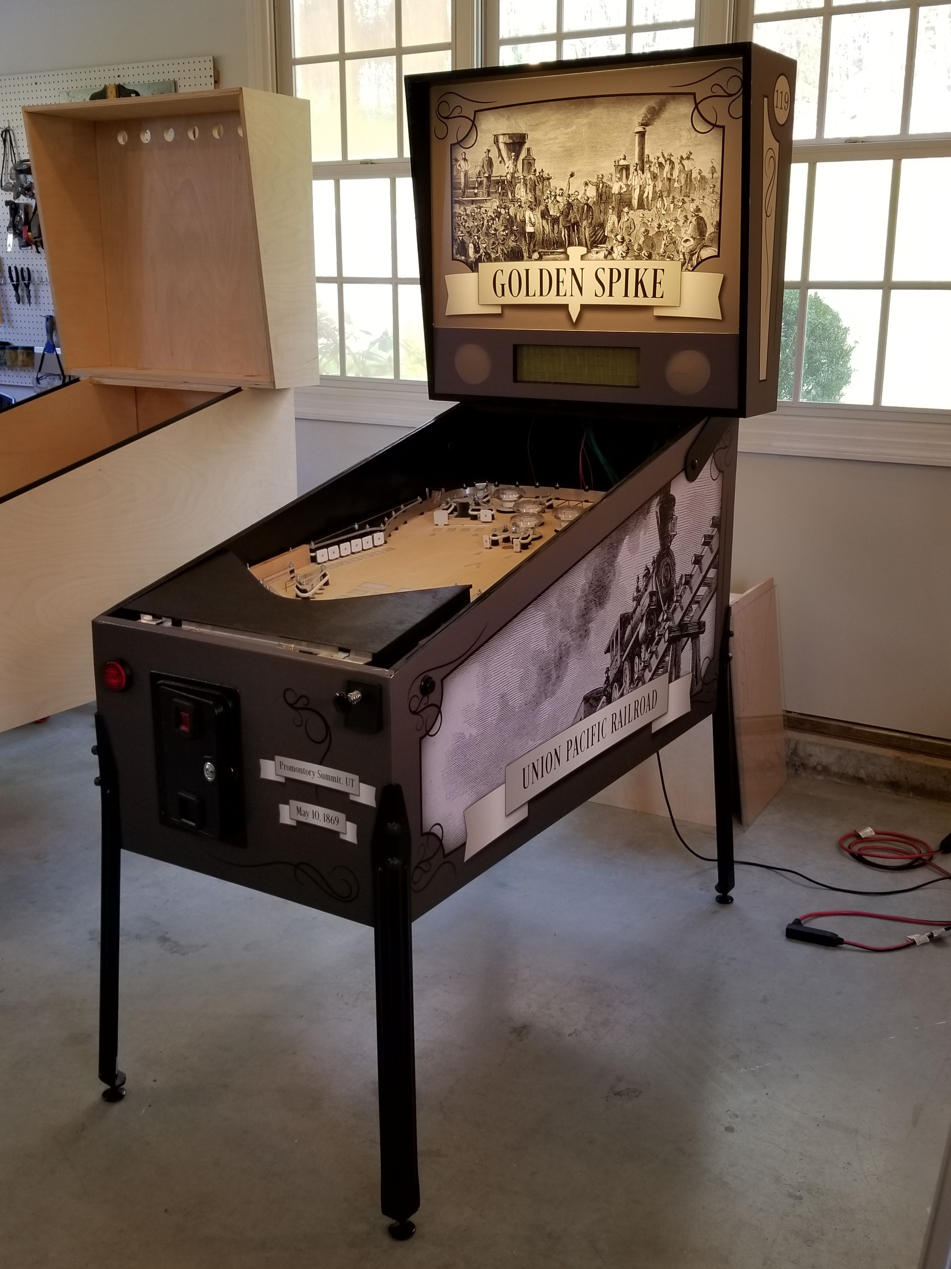
Not long after I finished mounting in the playfield brackets and lockdown bar, the artwork arrived. My Dad designed the artwork for me because I'm not very good with that kind of stuff. We had agreed earlier that a sepia color scheme matched the nature of the project, and that using those really old woodcarving-pressed newspaper images would really make the artwork pop. Indeed, it did.


The backbox sideart are mostly just flourishes that were common in the era.
The numbers of the locomotives are on it too: #60 on the left, and #119 on the right.
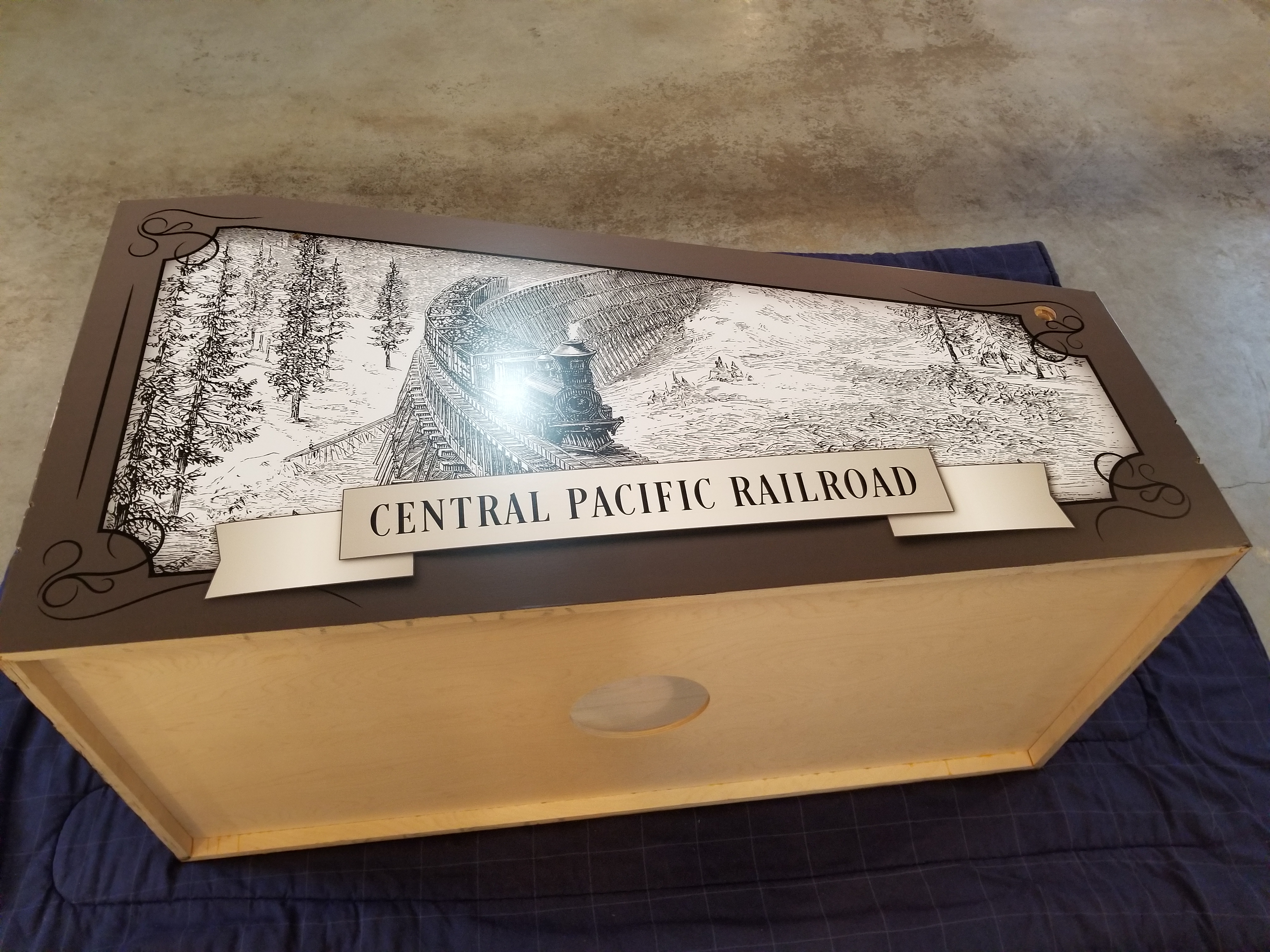

I love this sideart.
The sides of an assembled cabinet.
Not long after my Dad and I finished applying the artwork, I went back to work on populating the second playfield revision. I designed up and converted the plastics into another CNC file, and we machined those. Several 1/8th inch router bits shattered in the process.
These are some of the plastics that I designed and had cut.
All of the holes lined up perfectly the first time!
The scrap board that was beneath them.
After I finished wiring up the coils, I had to write up a program that would fire the coils when they were hit by the switches. It was very satisfying when I finally got the slingshots and pop bumpers working.
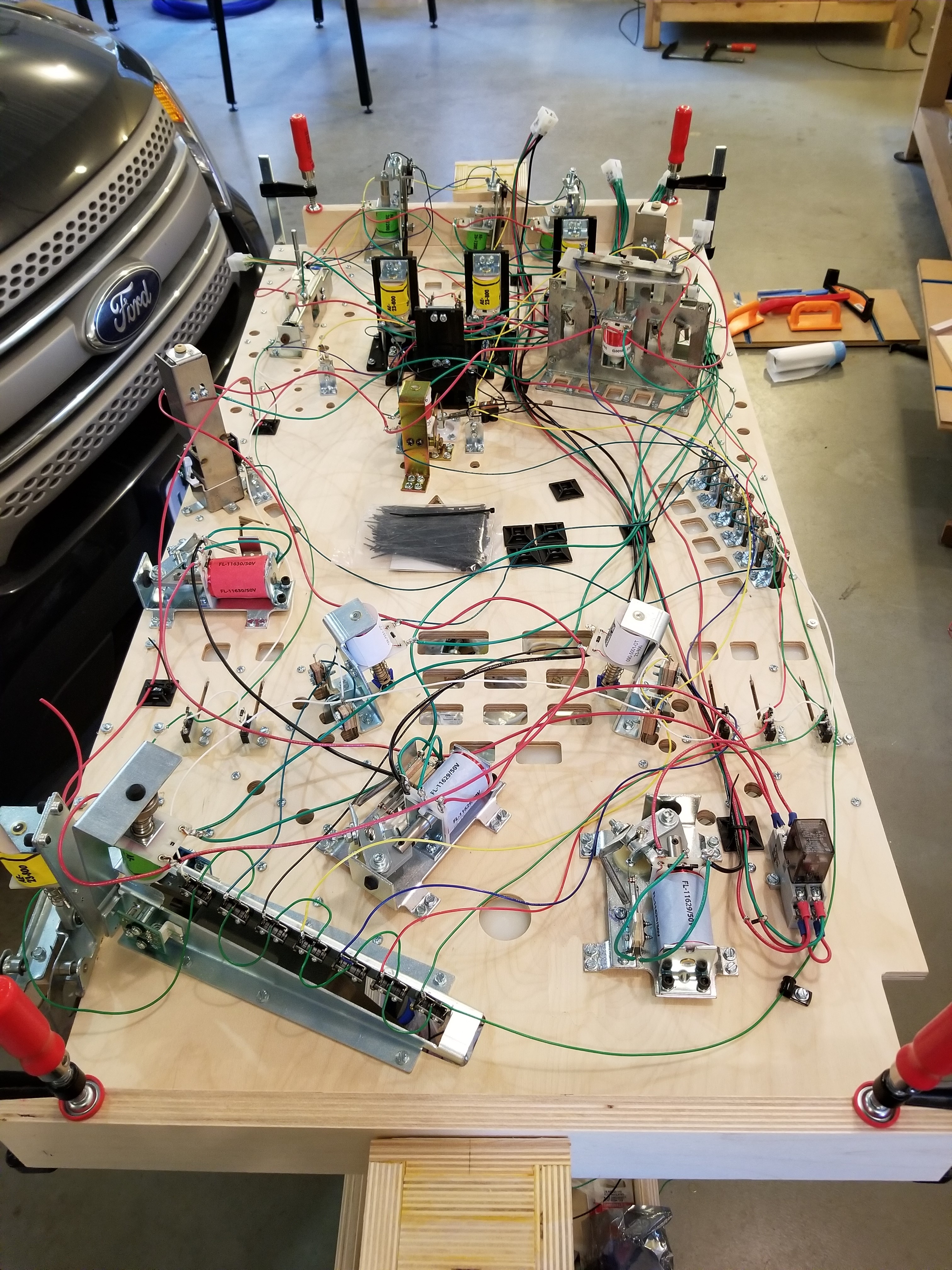
The wires for the switch matrix and the coils.
Testing my Pop Bumpers. This was before I reduced the coil fire interval -- it was a little long.
Testing the kickers and their optos. The playfield was not tilted yet.
After verifying that the coils were all well and good, I began on wiring up the lights. I used the SK6812 addressable LEDs to reduce the amount of wires needed (when compared to a lamp matrix). Some sources on the internet recommend against using them for playfield lights on pinball machines due to potential magnetic interference. I have not run into this issue at all.
The LEDs made life much simpler, although I had to design my own method of securing them to the playfield. I ended up designing a sort of spoon-shaped holder that grasps the LED and its wires and screws onto the playfield. I used about 45 on the second revision playfield.

All of the wires on the bottom of the REV-2 playfield. You can see the two strings of lights on the playfield.
Me testing the lights. I had a couple bugs that had to be fixed.
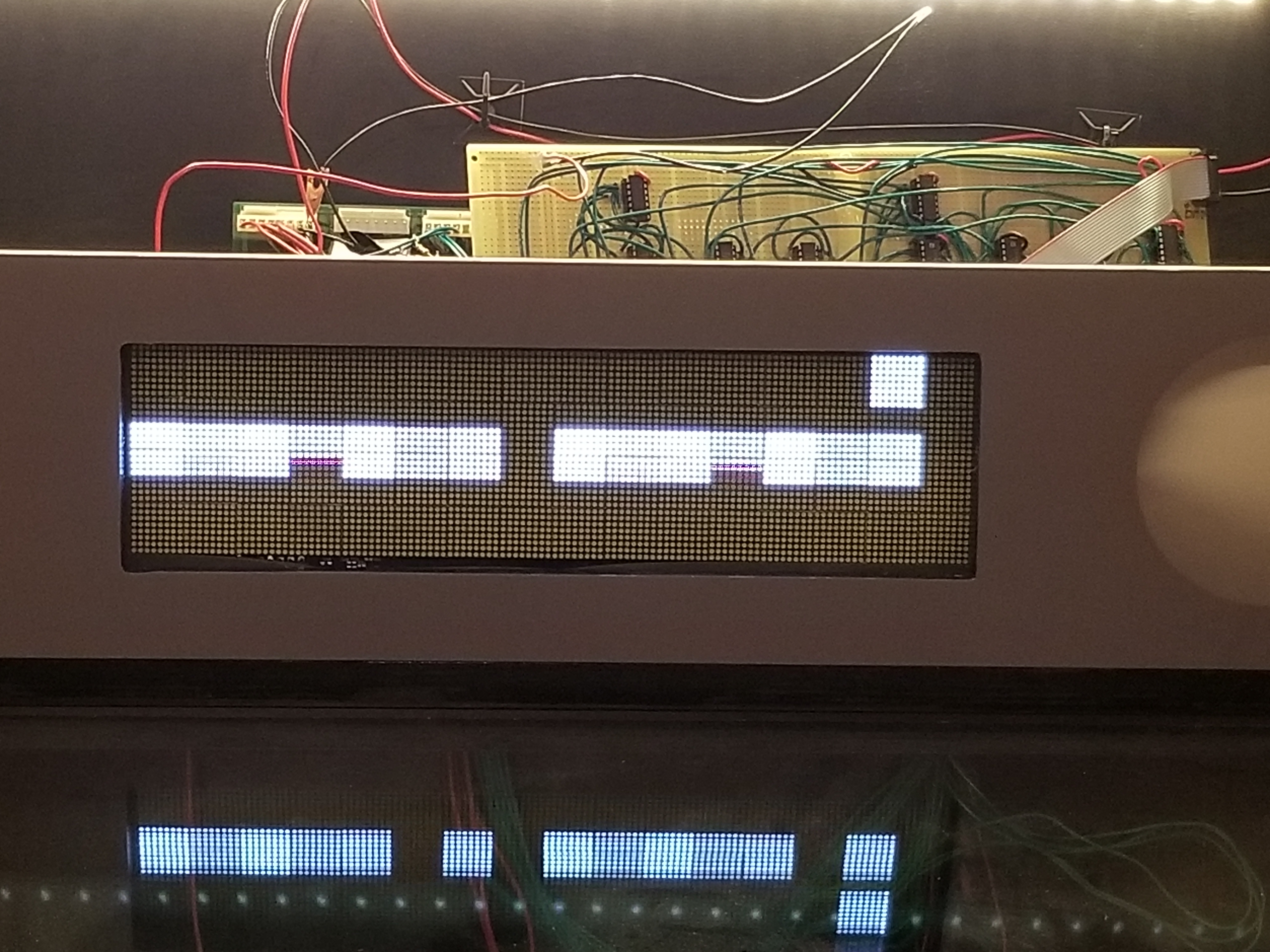
One of the last things I did before putting everything into the cabinet was figure out the Dot Matrix Display (DMD). Almost nobody on the internet has talked about running a pinball DMD with an Arduino. Looks like I'll be one of the first, then. Even if my explanation is really short.
Running a pinball DMD is actually a lot more straightforward than most people would think. It runs a lot like a standard monitor: left/right top/bottom. After looking at the datasheet for the VISHAY 128 x 32 display (I was using a drop in replacement from Xpin pinball), I just had to write a program that satisfied all of the data and control needs of the display.
Basically, it came down to:
- (If the first row) set ROW DATA high so the screen doesn't roll.
- (If not the first row) set ROW DATA low so you don't write to the same row.
- Write pixel data to SERIAL DATA
- Toggle the DOT CLOCK to advance pixel
- Repeat steps 3 & 4 127 times
- Disable the DISPLAY ENABLE to prevent row blurring
- Toggle the COLUMN LATCH to latch in the new row.
- Toggle the ROW CLOCK to start drawing the next row.
- Re-enable the DISPLAY ENABLE.
Not all of the signals the display needs are active HIGH. I'd recommend reading the datasheet before attempting to program it. Also, feel free to look at my code. (NOTE: This is the old DMD program. The new Master Controller and DMD programs are included with the revision 2 pinball hardware on the Downloads page.)
This was one of the first iterations of DMD code that worked. As you can see, switch debouncing was nonexistant in the main program at the time of taking this video. This would be fixed when I rewrote the Master Controller program from scratch. The flashing/strobing in the video is the camera lens catching the DMD's refresh rate.
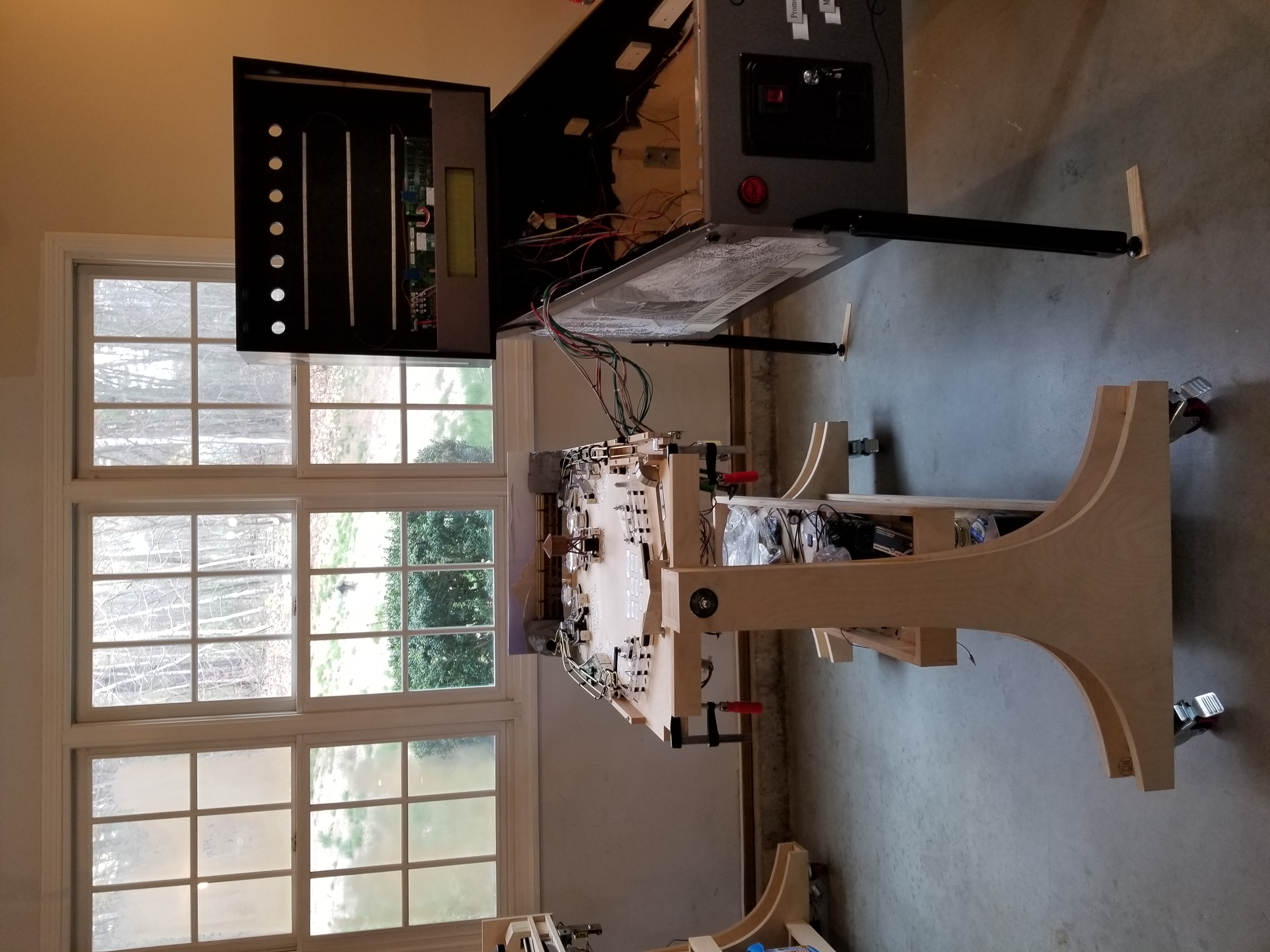
All of my electronics and wiring had been verified tested and working, so it came time to mount it all into the cabinet. Before I mounted it into the cabinet, I wired up the cabinet switches. After all that was working, I had my Dad help me lift and move the playfield into the cabinet. It is very easy to forget how heavy they can get with everything mounted on.

The old cabinet electronics.
About 7 cables connect the driver board to the playfield.

The second playfield before being mounted into the cabinet.
I designed and 3D printed all the inserts with translucent filament.
It works really well.
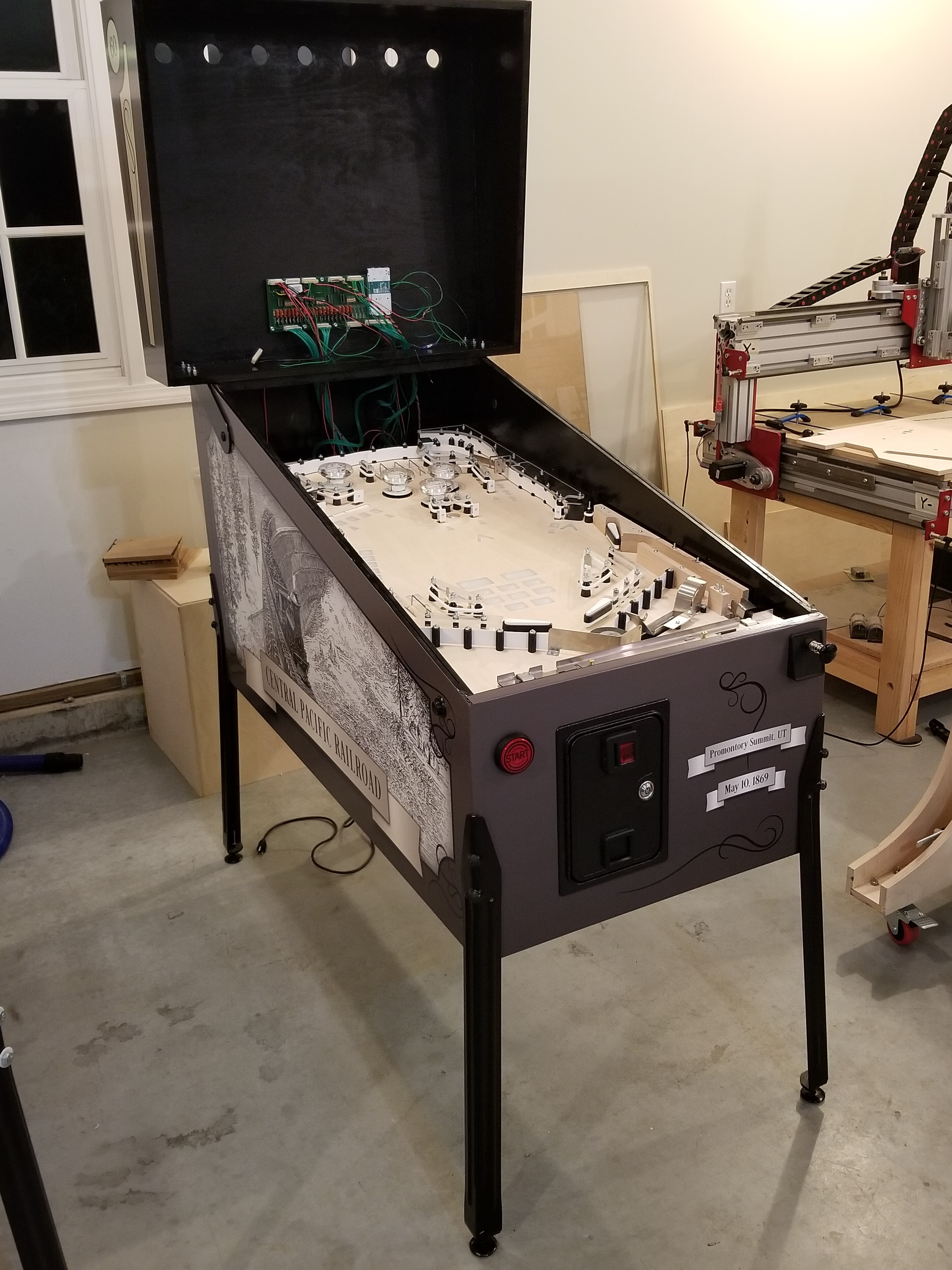
The playfield mounted in the cabinet.
We hadn't made the metal walls yet.
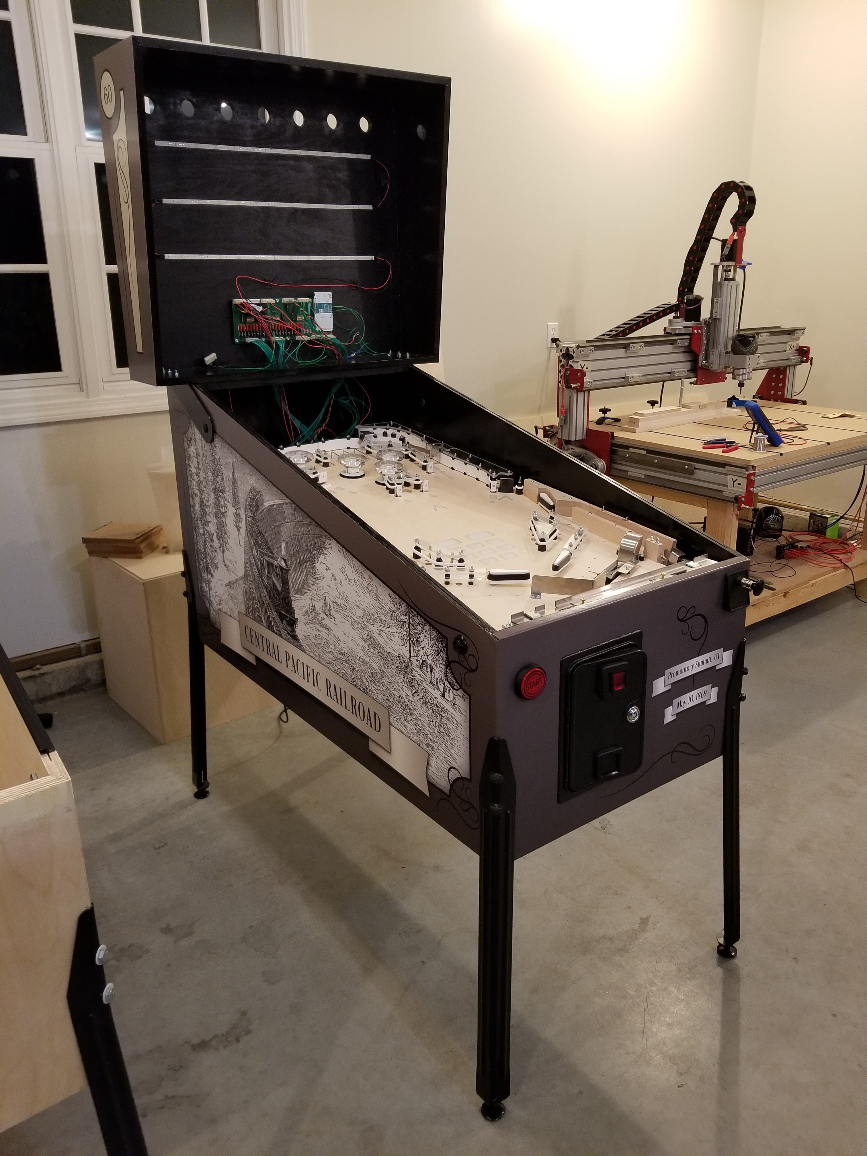
The backlighting for the marquee was just a 6'
piece of 12v LED striplighting cut into 2' lengths.
And finally, after 326 hours invested over the span of about 6 months, I had Golden Spike. I would end up spending an additional 520 hours over another 2 years before it was finished.

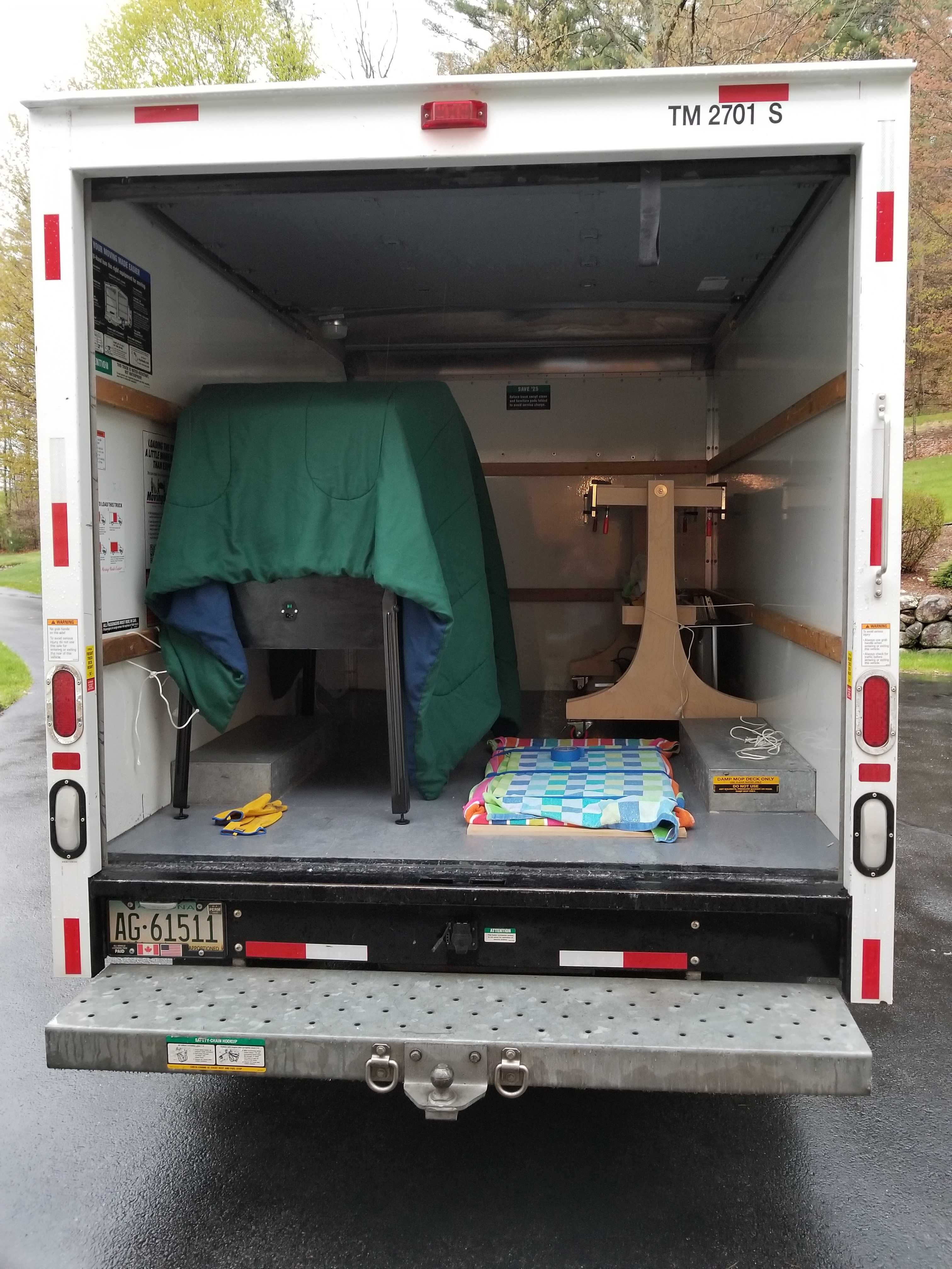
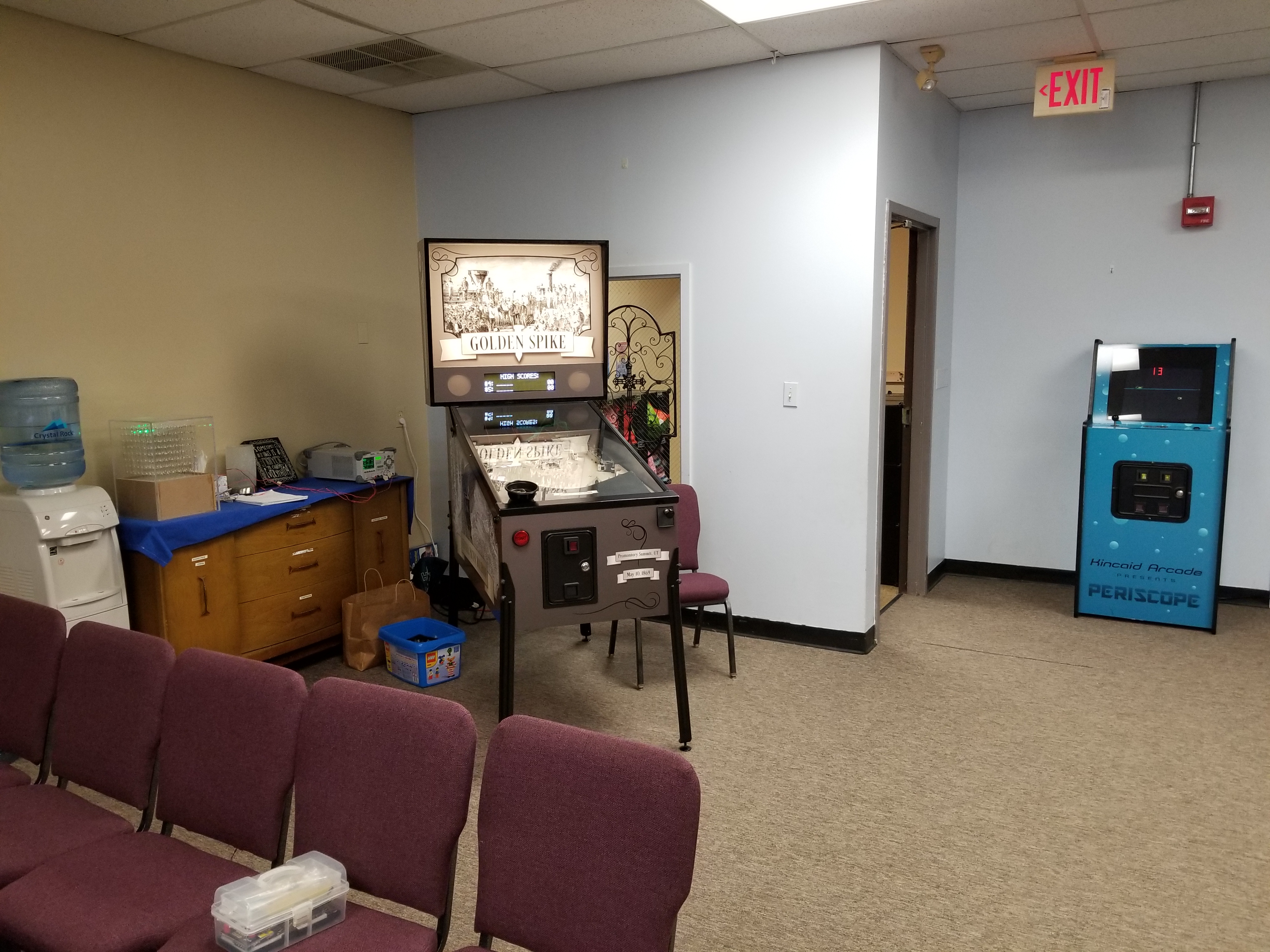
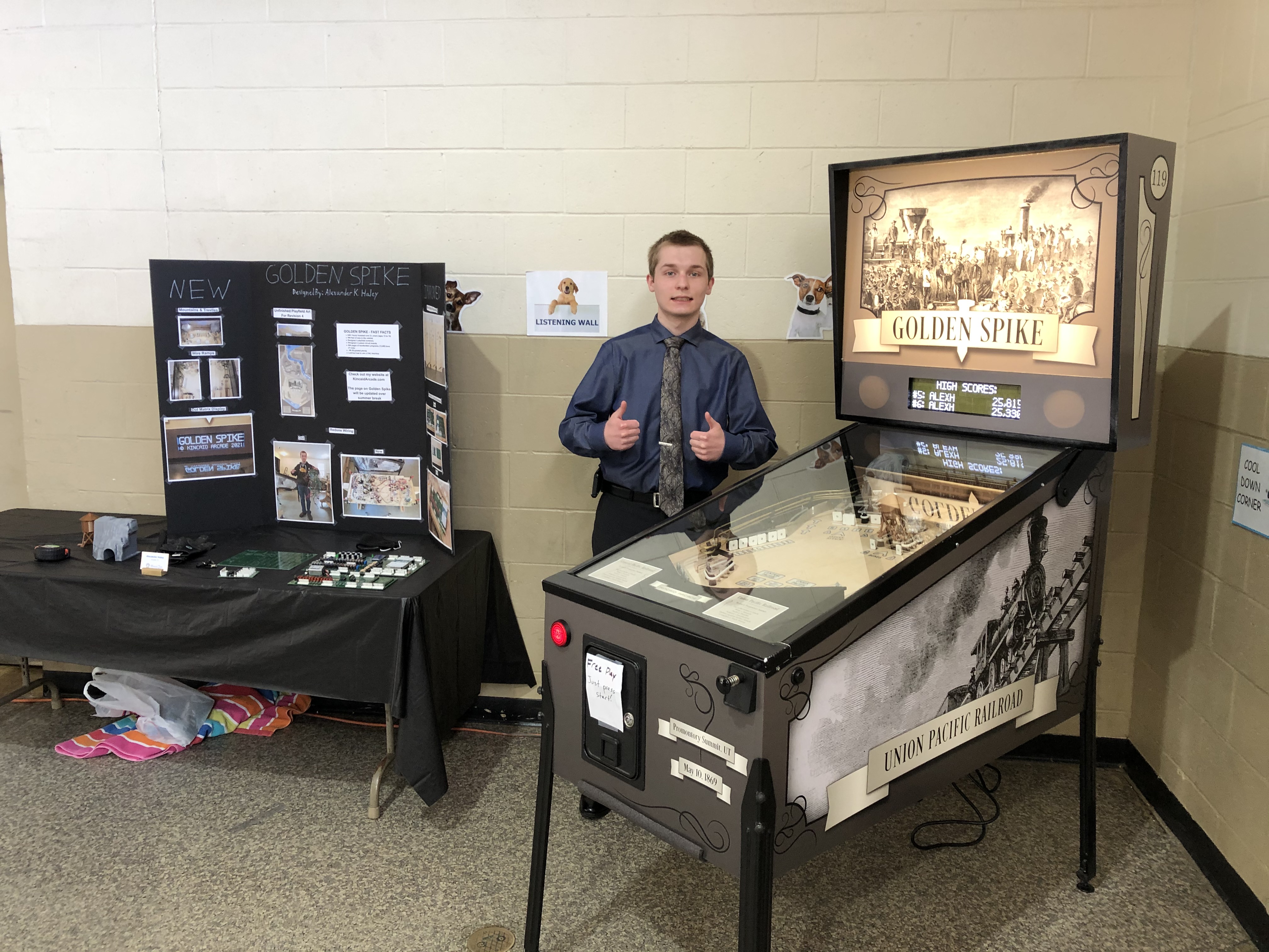
Here it is, all loaded up in a U-haul for transportation to the school exhibition, which was on May 10th, 2019 -- the exact 150th anniversary of the completion of the Transcontinental Railroad! Unfortunately, I had not installed a coin counter yet so I don't know how many games it got during the expo.
It was really cute watching the little kindergarteners team up to press the flipper buttons as their arms weren't long enough to reach them both! Their exited gasps of "Oh?" and "WOW!" when it dissapeared into a VUK and shot back out at the flippers were absolutely priceless.
Here's a gameplay video my Dad shot of me playing it after the exposition. The bottom right flipper coil burned up the game immediately after the one recorded in this video. I chose to have the DMD disabled for the exposition because the DMD Arduino would sometimes lose communication with the Master Arduino and start throwing out random gibberish. I figured out better means of communication between the two when I rewrote the main program later on.
Finishing Golden Spike
There was much that needed to be done to finish Golden Spike, and it certainly seemed a bit overwhelming at the time. However, as Henry Ford once said, "Nothing is particularly hard if you divide it into small jobs," so I picked an item and began to work on it (the DMD and associated circuitry).
The main problem with directly driving the DMD with the Arduino was the amount of digitalWrites() required to toggle all of the inputs on the DMD, and the fact that it takes a LONG time for the Arduino to prepare the frame before pushing it to the output pins. In short, there was noticeable display flicker. I briefly considered using a Raspberry Pi or some other more powerful development board as a means of pushing frames to the DMD faster, but that would require loads of time learning to use a new development environment or programming language so I abandoned that idea pretty quickly. My next idea was to use the experience I had gained with TTL logic from PERISCOPE to design some sort of primitive frame buffer hardware. The idea was to have two different banks of screen RAM: one that was being written to by the DMD Arduino and another that was being drawn to the display. As soon as the Arduino finished putting the next frame into the frame buffer, the role of the frame buffers would swap and the new image would be drawn onto the screen. This would provide the dual benefit of ensuring that there is always something being drawn to the screen and freeing up program runtime on the already overworked Arduino to render frames.
With this goal in mind, I began to draw up the schematic. There was nothing particularly difficult with this design, although handling all of the data selection logic was a bit tedious. The experience gained from this basic double-buffered design would later be used in the Vector RAM circuits on the Kincaid Arcade Vector Graphics Card.
Prototyping the board would also go relatively quickly. Here is the prototype:

This picture was taken much later and is missing the Arduino and the logic chips.
Despite not taking a long time to prototype, the board took awhile to debug and adjust. Even something as simple as one wire in the wrong spot can seriously consume your day.

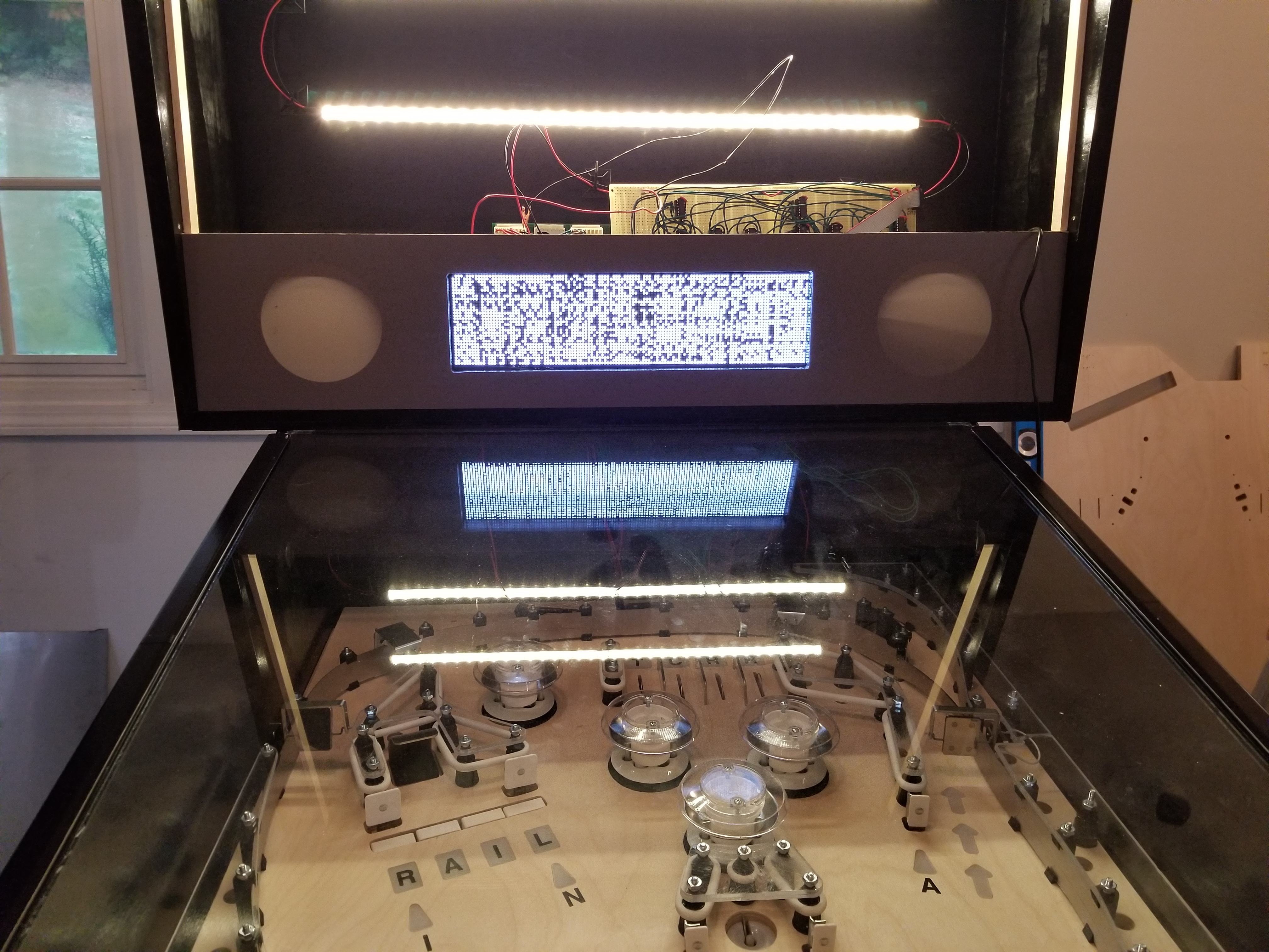
Like all designs, working out issues can be frustrating. Eventually, it worked:
The DMD above is displaying an eight shade grayscale (off is included). Some of the shades were out of order and poorly adjusted, which was caused by some timing issues. Normally, you would expect this to work by PWMing each pixel as the display draws it, but I soon realized that that wouldn't be possible since the DMD draws an entire line at any given moment, meaning that the whole line would be PWMed. Instead, I have the DMD draw three sub-frames as a part of each frame. Each sub-frame is drawn with a different brightness. By drawing the same object across the different frames, it would appear to be a different brightness. Mixing and matching would get 8 different shades of gray (including off).
I had not gotten the shades of the prototype DMD driver board working before my school asked me to bring in my projects again for a special event -- none other then Frank Brogan, the Assistant Secretary of Education to Betsy DeVos, was visiting my school, and wanted to hear me talk about my projects and the Eden Exposition! (I explain the Eden Exposition on the aboutme page) So, we packed my projects up into a U-haul and brought Golden Spike, PERISCOPE, and my LED Cube to school. Not only did I get to meet Mr. Brogan, but I also met the superintendent of New Hampshire education as well, and I got to shake all their hands! Definitely a pretty neat experience.
Less than a week later, COVID locked everything down and all of a sudden I was at home much more of the day. It wasn't until after the schoolyear ended that I resumed working on Golden Spike, though, since I was still designing the Kincaid Arcade Vector System (the big project of the year).
Once I was able to start working on it again, one of the first things that I did was fix an issue with the backbox hinges. When I had initially calculated where to place the holes on the cabinet and backbox, I did not account for the height of the siderails and glass. Needless to say, the backbox would not lay down correctly. Since the holes had to be placed quite close to where they were originally, my Dad suggested that we shove in and glue dowels to plug the old holes before drilling new holes. This is what we ended up doing (I did not take pictures of the holes in the backbox, unfortunately).
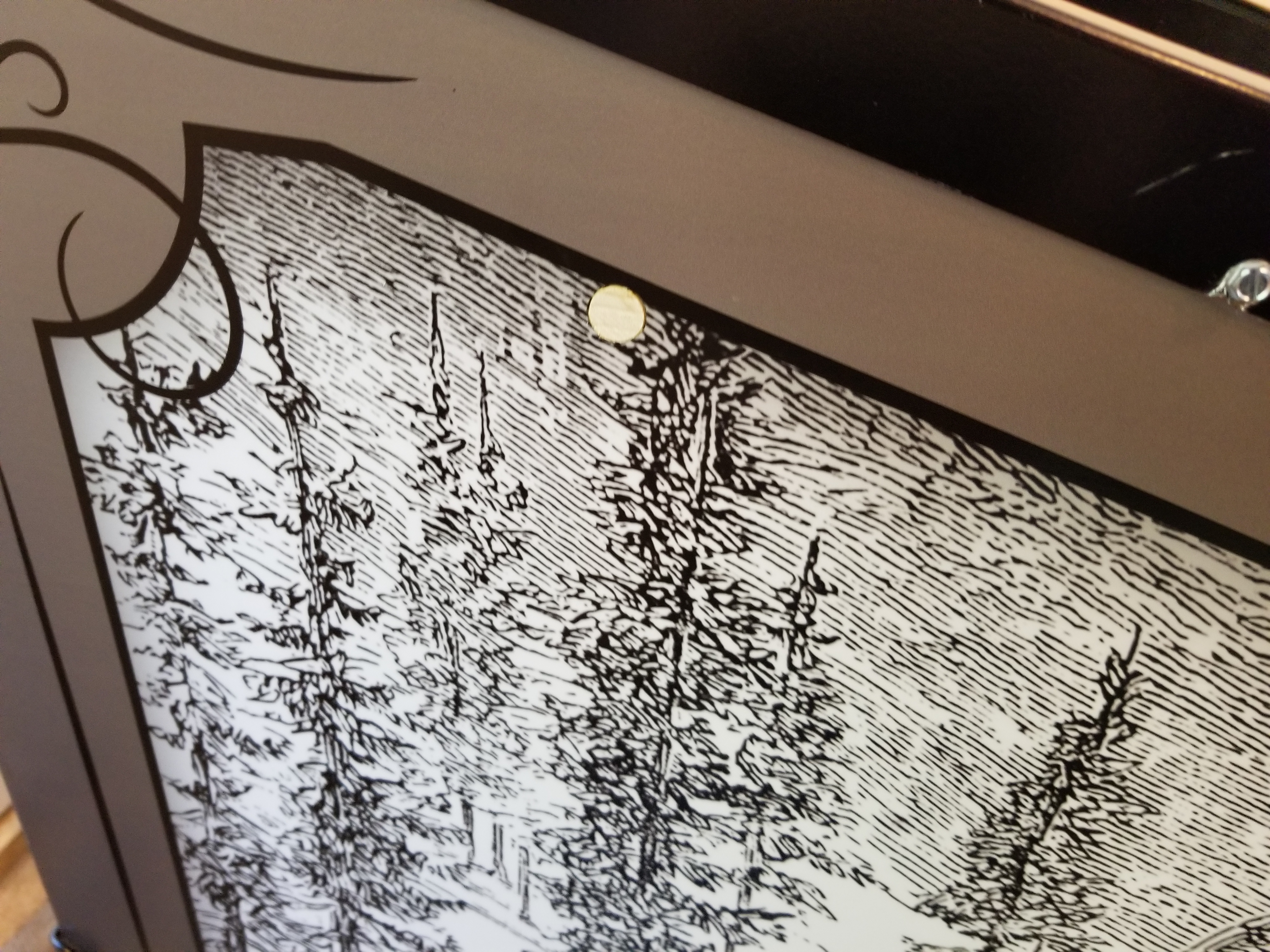
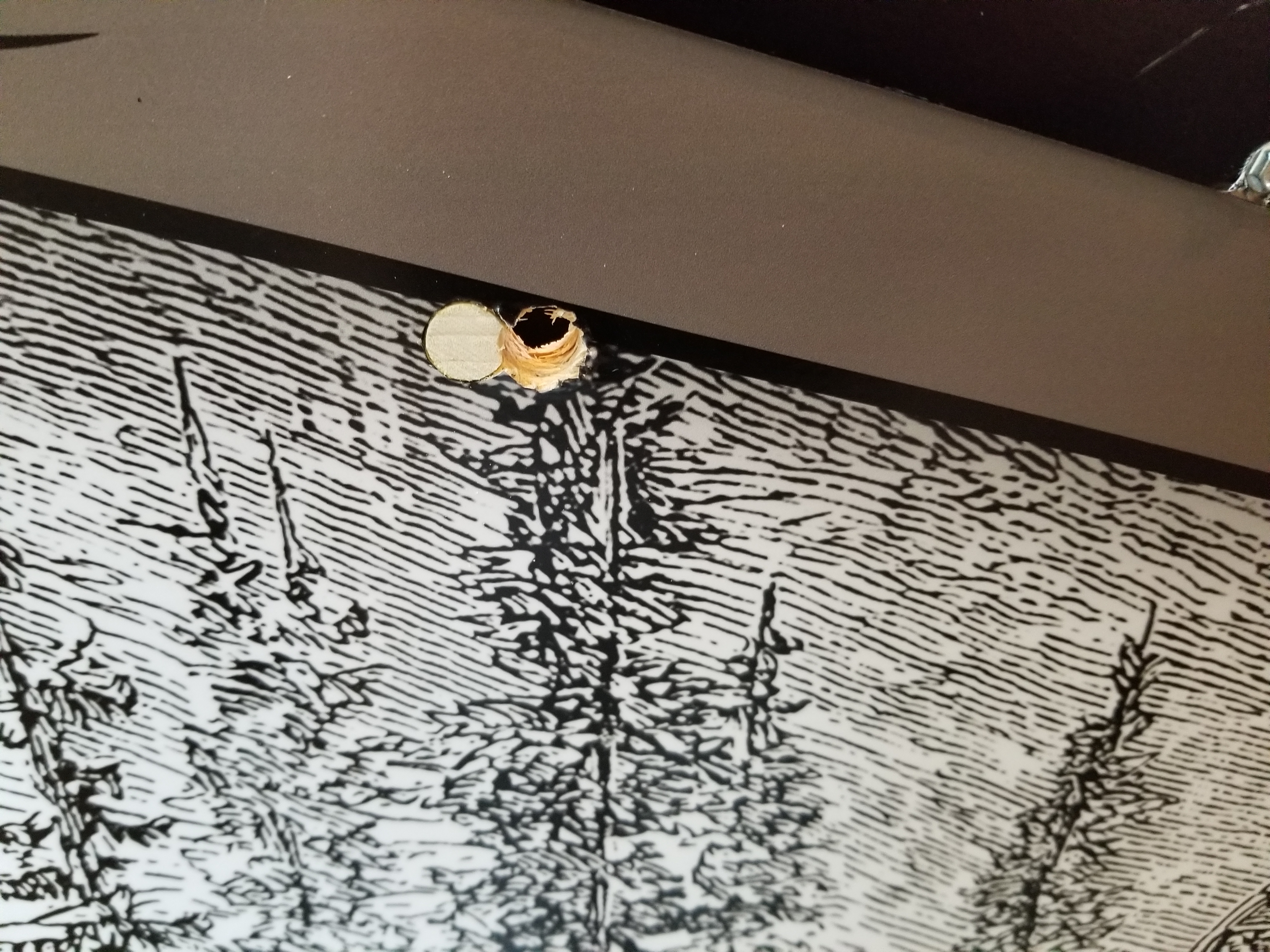
The backbox sat half an inch lower before it was fixed, and would sit at an awkward angle. Glad it's fixed.
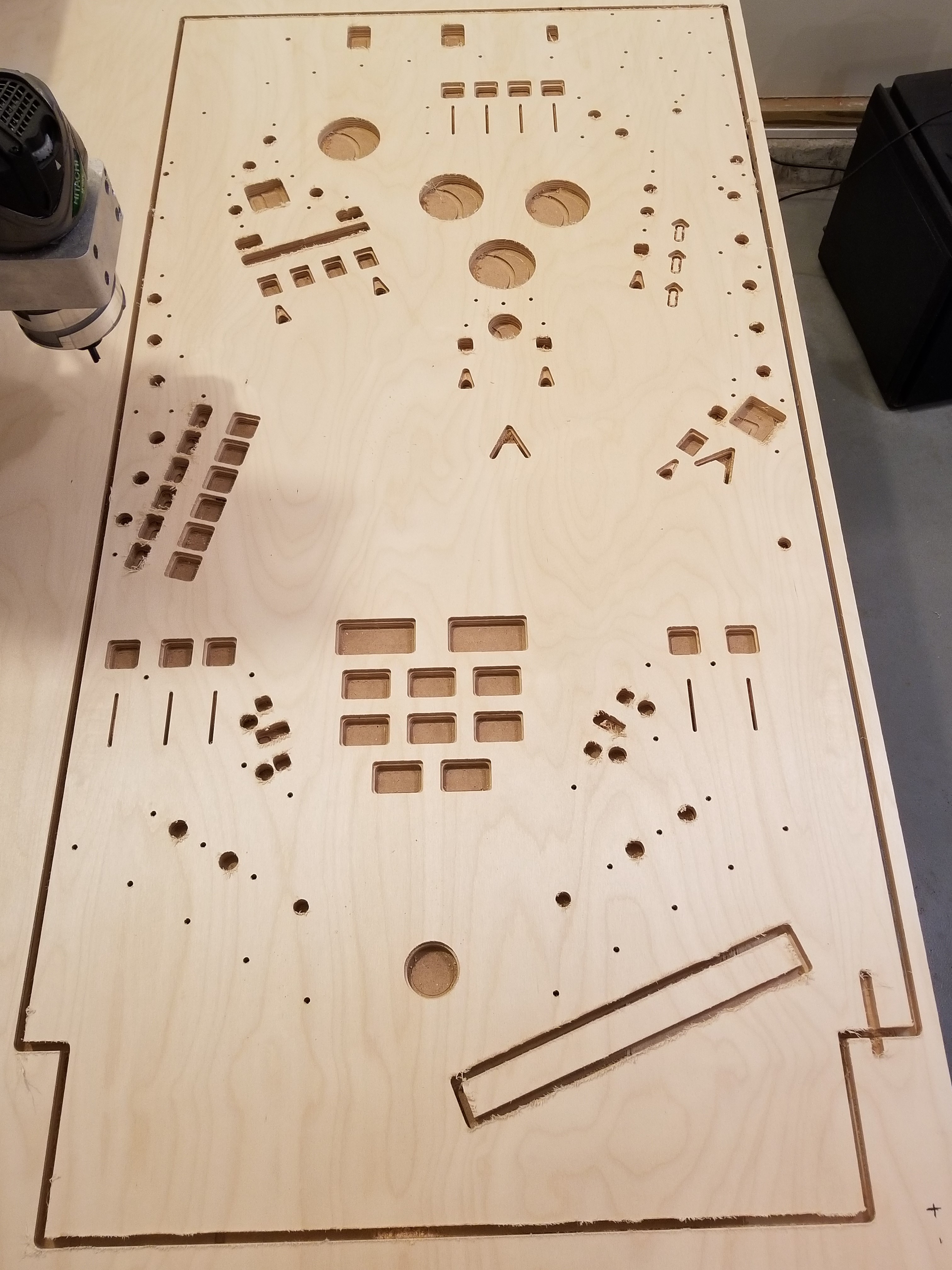
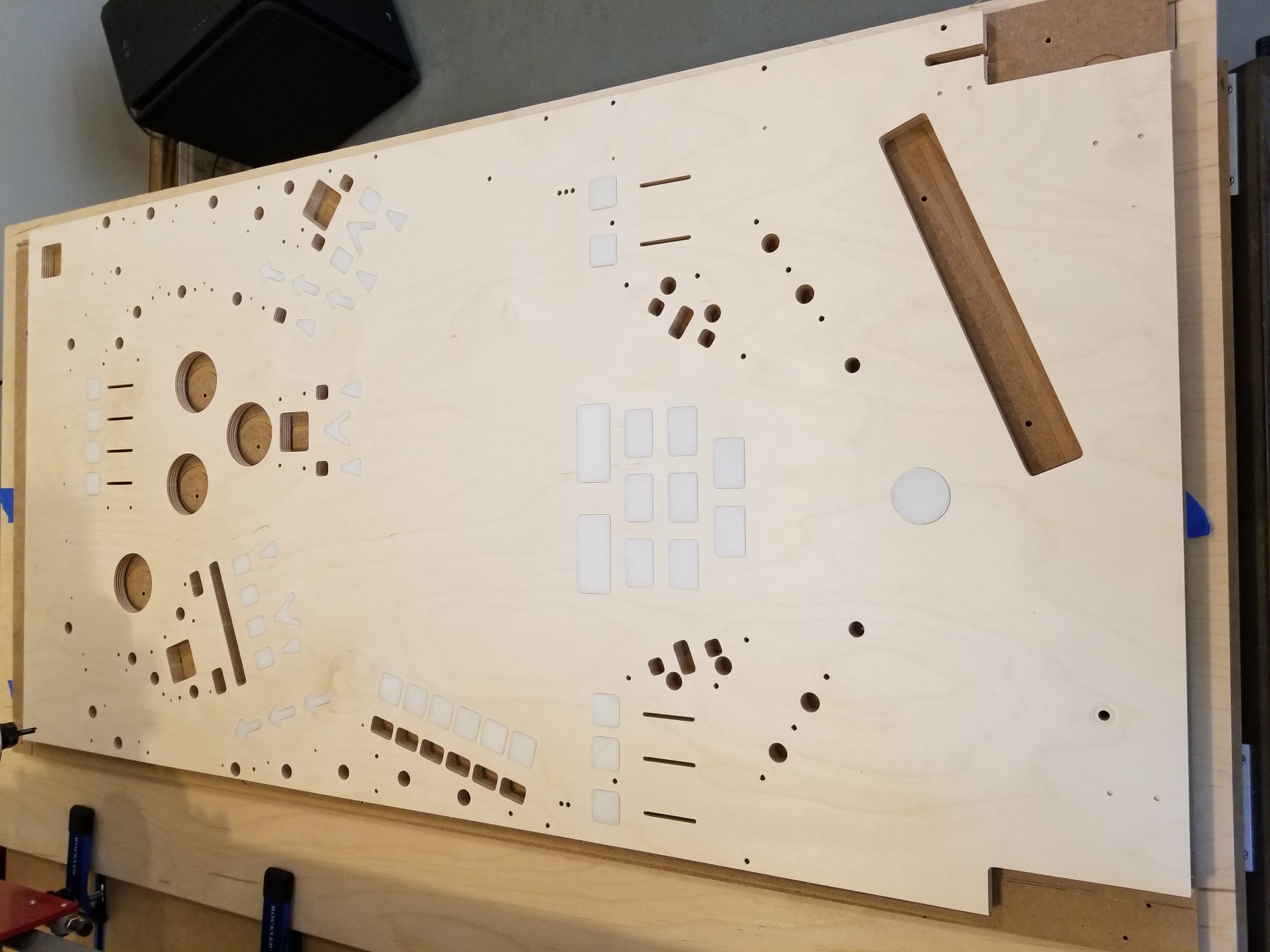
After fixing the backbox, I made a whole bunch of changes to my playfield design file based on all of the issues I had with revision 2. From there it was a matter of milling the playfield and populating it, although I wouldn't get around to populating it for awhile. Notice how many changes I made to this revision: the shooter curve has been removed, the second right flipper has been removed, the right orbit has been modified, the trestle area looks kinda bare, and the supply tower kicker hole has been replaced with a VuK.
From left to right, top to bottom: 1) The machine milling ⅛ holes, with several ¼ holes drilled with screws added to help hold the playfield in place while being milled, 2) The playfield all cut out, unsanded, 3) The playfield with all of the new 3d-printed inserts test-fit, 4) All of the inserts at the side of the playfield, and 5) The playfield with inserts glued in before being sanded.

Designing New Hardware
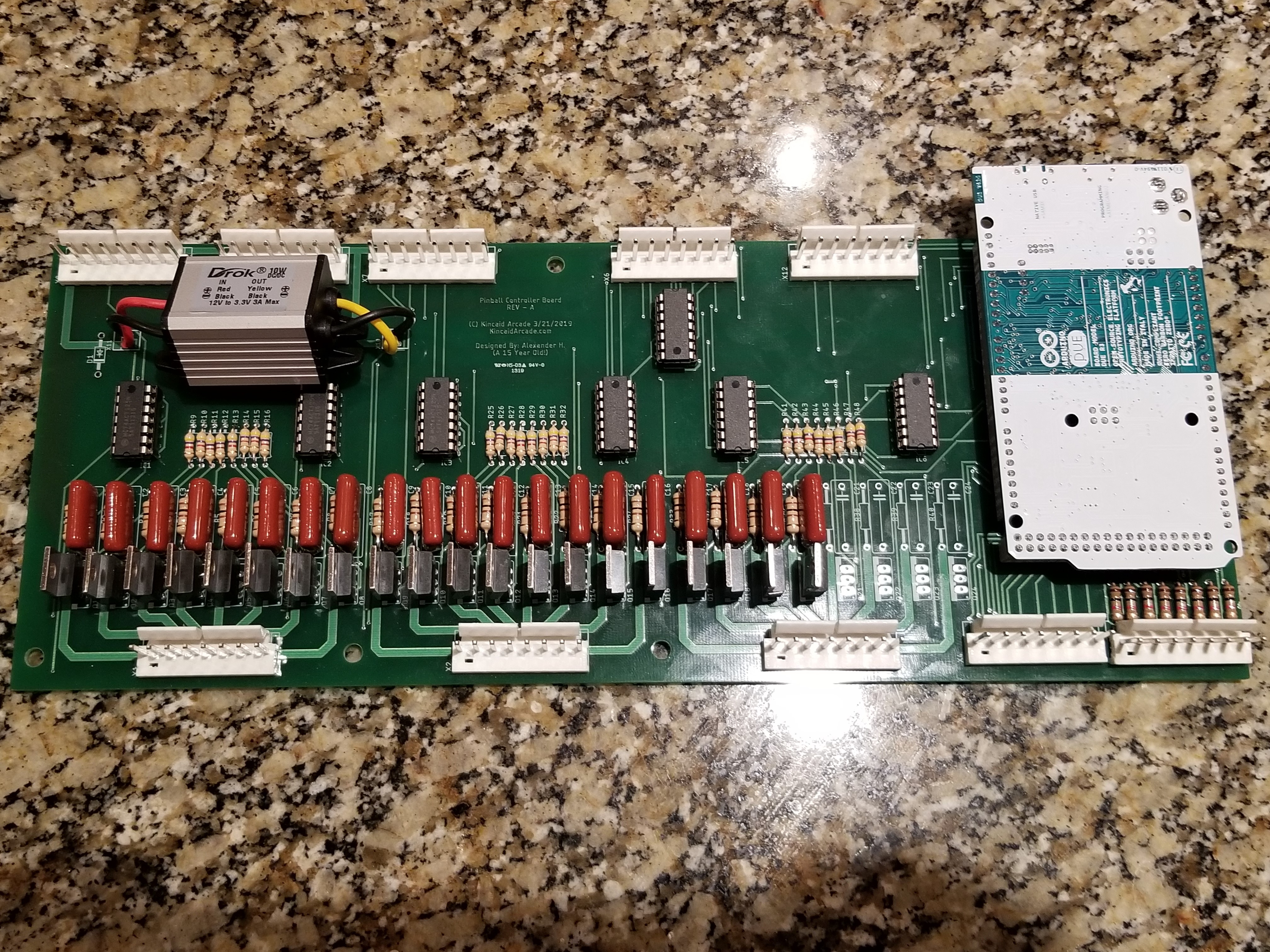
At this point in the development process, I had playfield revision #3 ready to be populated with parts and wired up. However, the old hardware I had designed was beginning to become inadequate as I added things I hadn't previously considered adding. The new DMD Driver prototype was finished and it was becoming a bit of a hassle to deal with all its wires. Oh, and did I mention that I accidentally shorted something out that caused the "magic smoke" to be released from the old hardware? Yeah, it was time to make the transition to new hardware. I had been considering doing this for awhile, although the episode with the magic smoke really expedited the timeline for that. Rather than fix the old boards, I began to design new ones. Here is what I came up with:
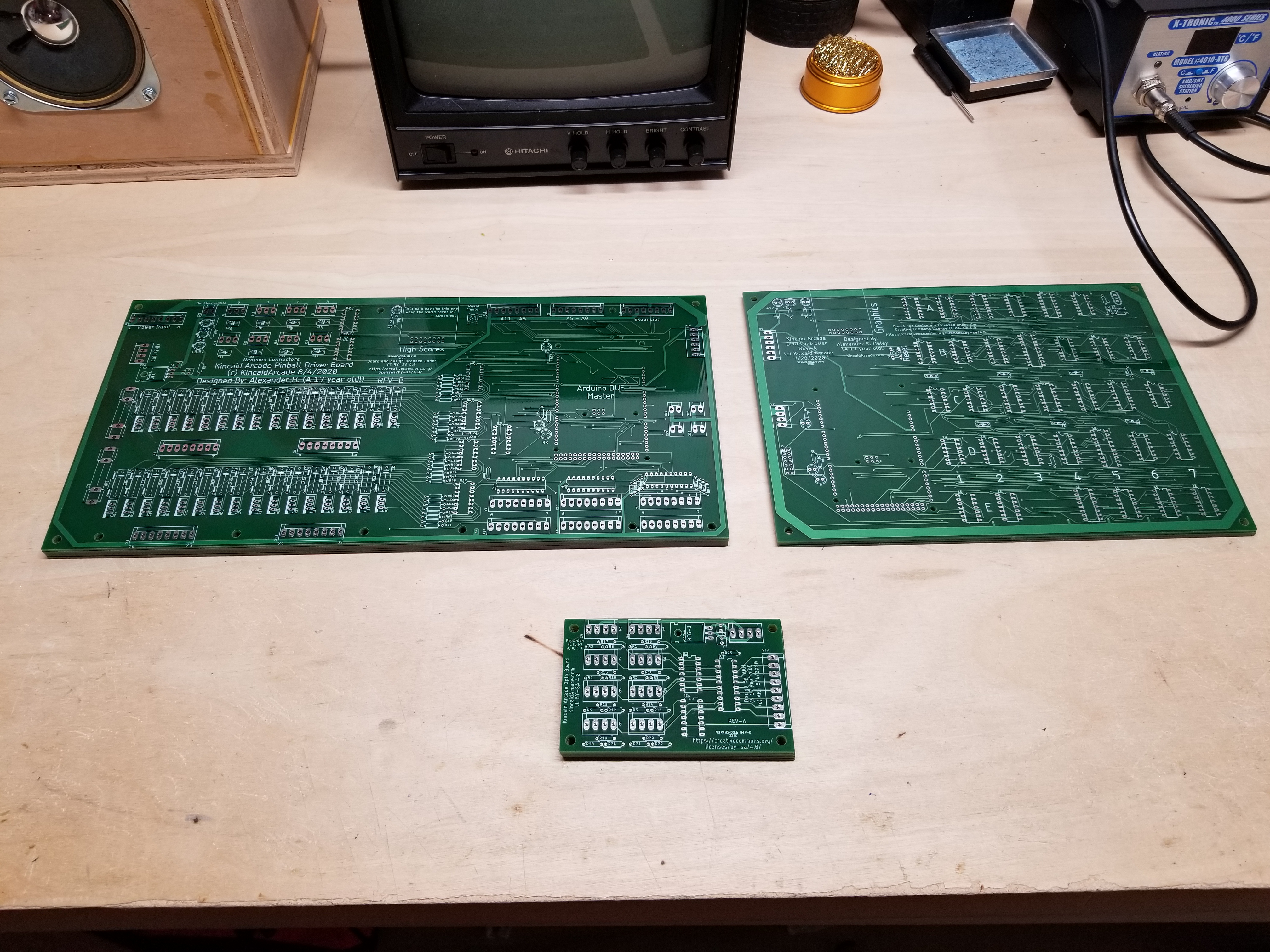
Top left: the REV-2 Kincaid Arcade Pinball Driver Board, Top Right: the REV-A Kincaid Arcade DMD Driver Board, and at the bottom was a new board I designed called the Kincaid Arcade Opto-To-Switch-Matrix Board. Gee, I wonder what it does. :)
The new Driver Board had many improvements over the old one: more connectors for hooking things up, an SD card reader to store high scores and other stuff, a 128-switch matrix instead of a 64-switch matrix, buffers on the inputs, 32 instead of 24 coil channels, fuses for the coil driver channels, a built-in 3.3 volt regulator and power lights to tell me at a glance if something isn't working, and an expansion port with voltages and serial pins if I ever decided to add a sound controller board. My skills with analog circuits are not very good right now, so I don't see that happening any time soon. On the bright side, I will be going to college for Electrical Engineering this fall, so I'll have an an opportunity to learn how to do all that stuff the right way.
The DMD controller board is basically just a circuit board of everything I had on my prototype, although I did add power lights and an SD card reader to store bitmap graphics in case the Arduino ran out of memory.
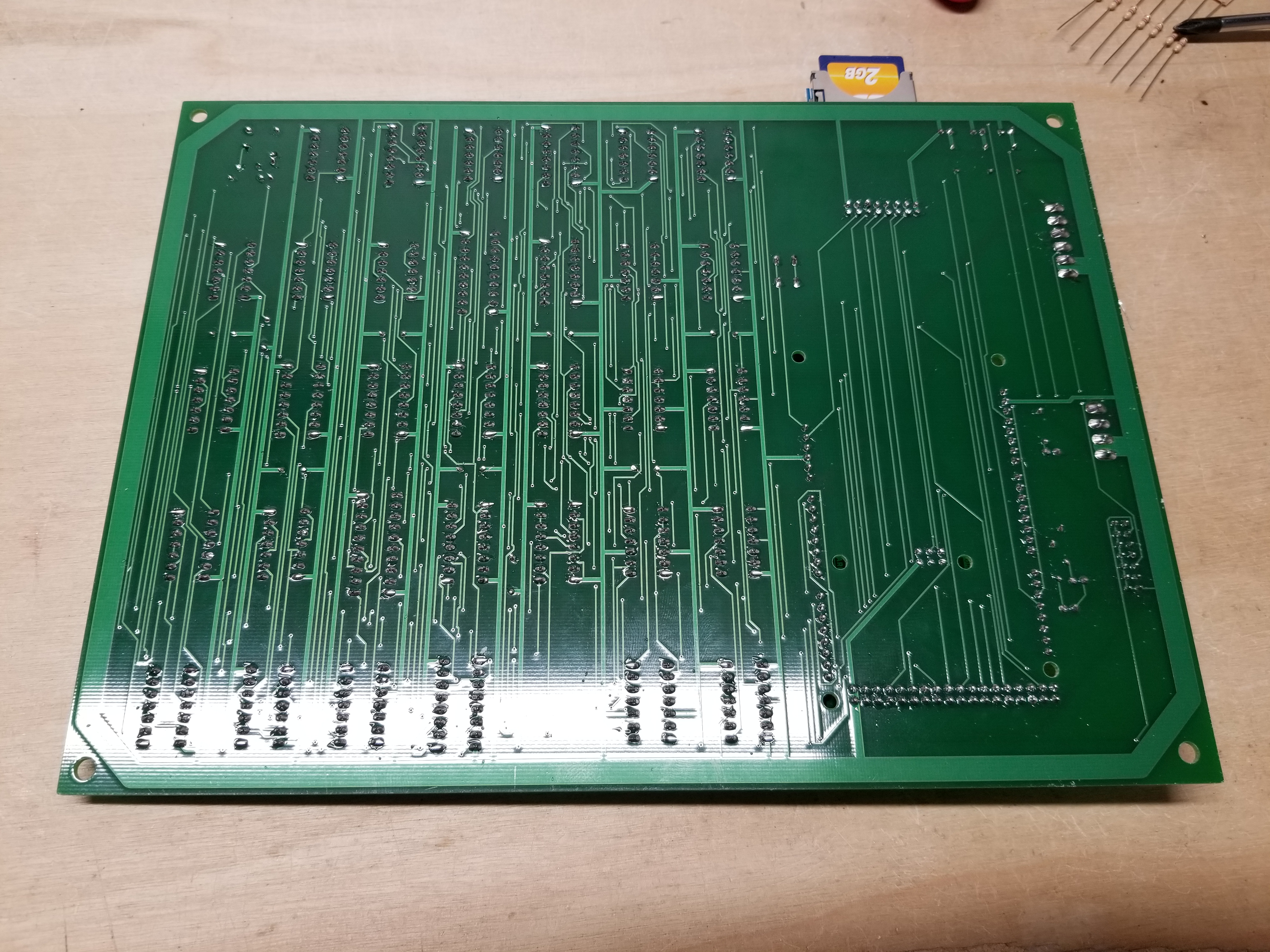
Here are some close-ups of the boards I designed:

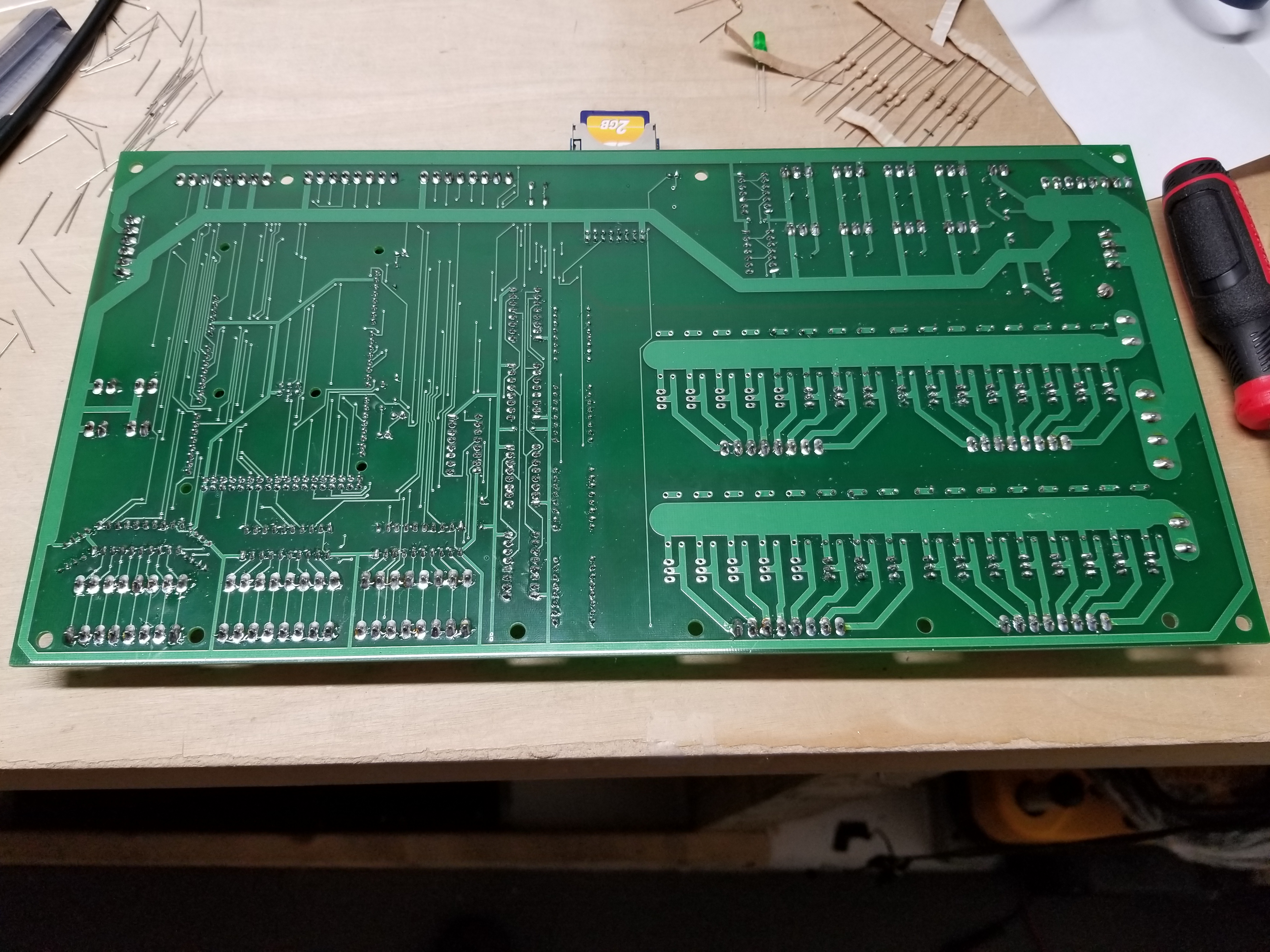
The new Pinball Driver Board

The DMD Driver Board
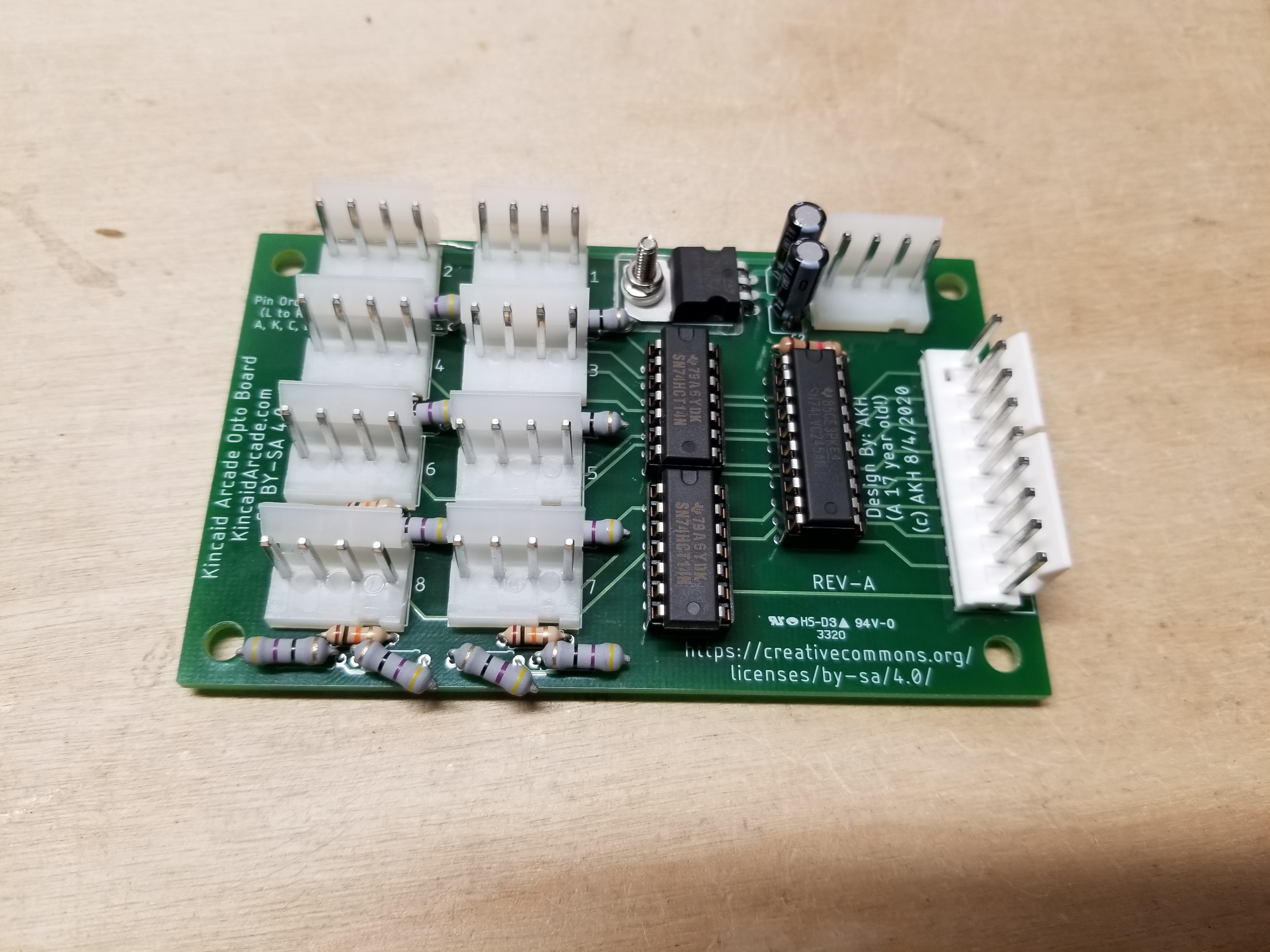
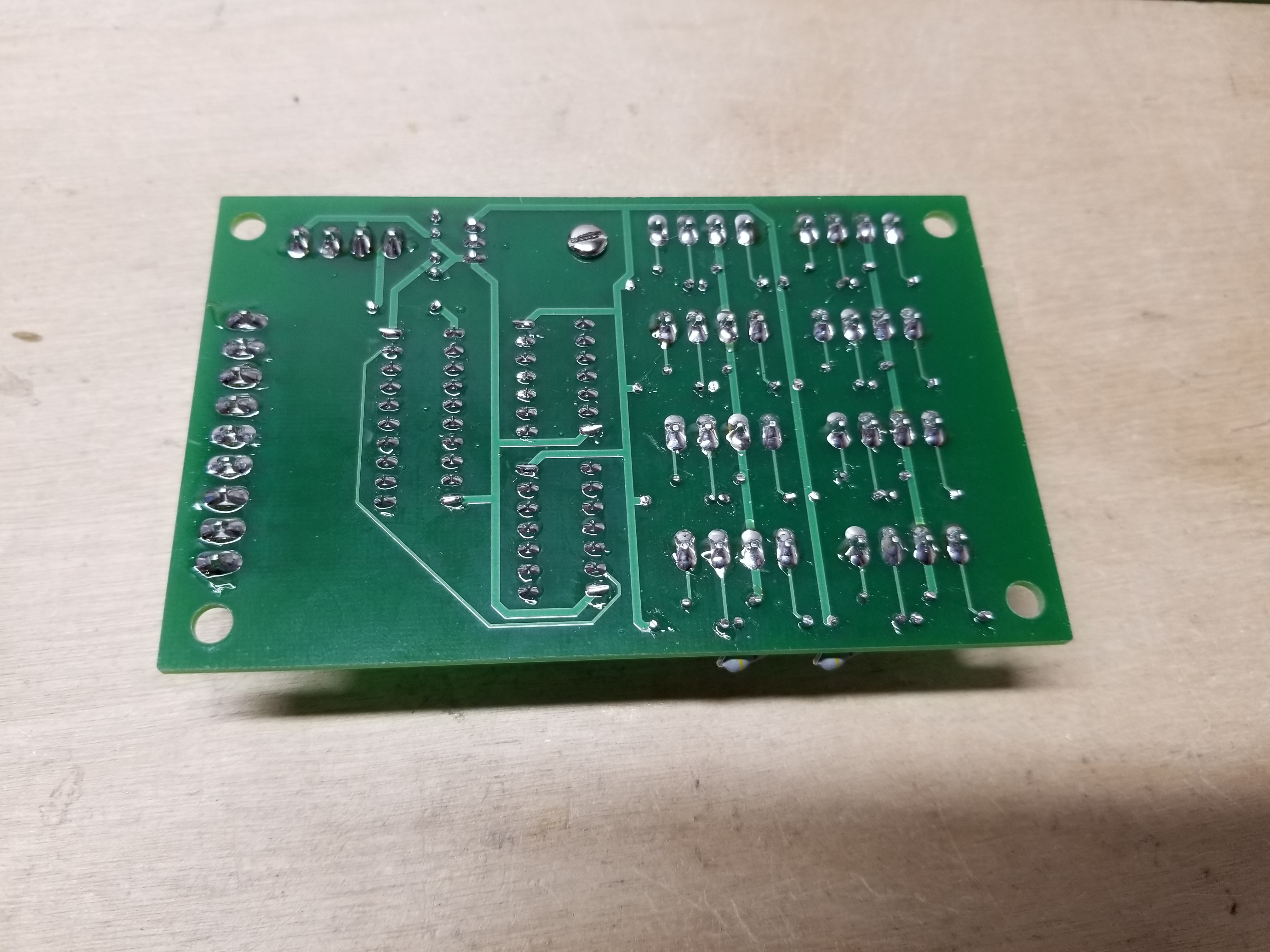
And the Opto-To-Switch-Matrix Board. Ever notice how the pins on the VuKs ("Scoop Weldment Assemblies") that Pinballlife sells are labelled A,K,C,E? Well, I labelled the corresponding pins on this little board as well. If you've ever had any trouble figuring out what to do with those letters, the schematics for the board are on the Downloads page!
While I was at it, I also made one more little circuit board: a coil driver tester for my new Pinball Driver Board. The idea is that it replaces each coil with an LED that will light up when it turns on. If I ever do a 3rd revision Pinball Driver Board, I will incorporate these LEDs into each coil driver channel; they're SUPER useful.
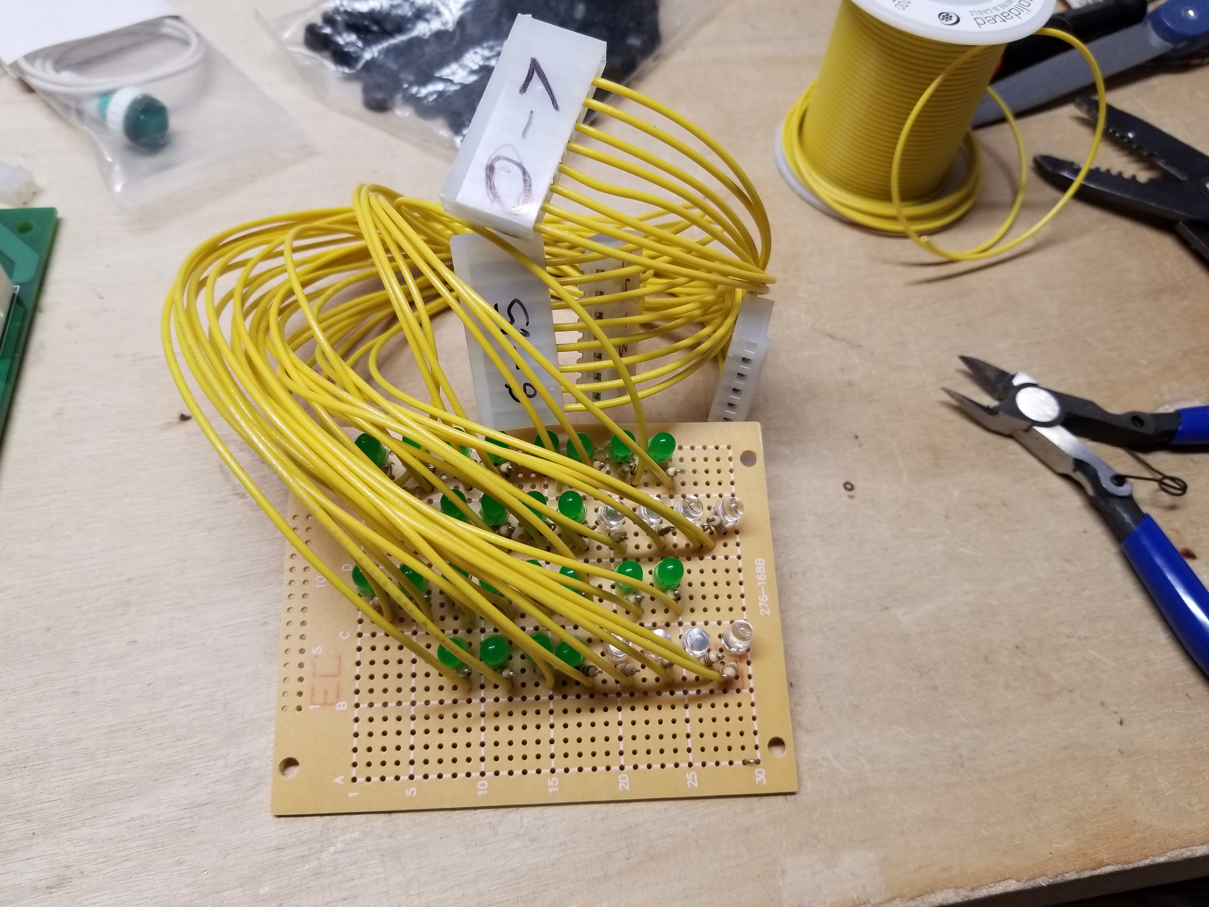
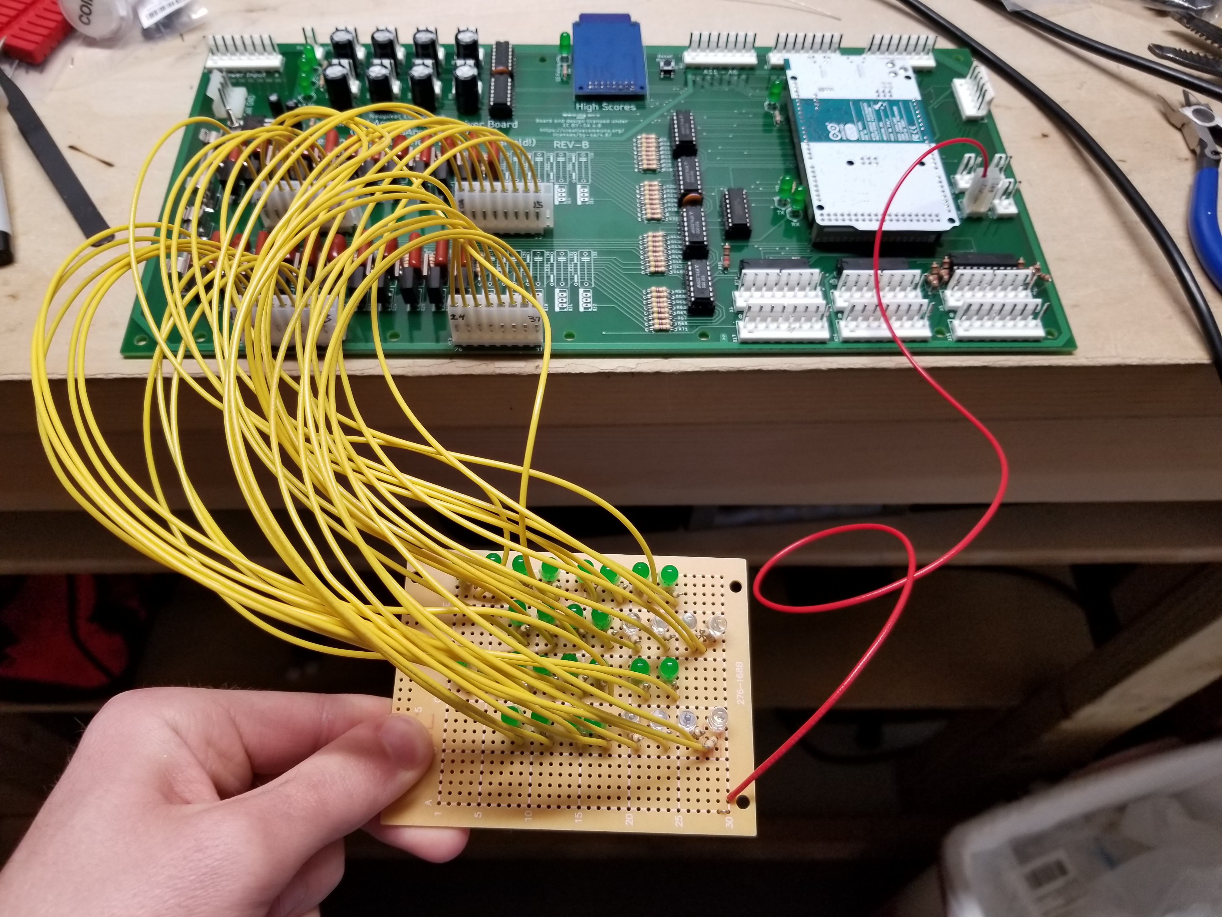
The tester. Nothing difficult; just an LED and resistor for each coil channel. Uses 5 volts for each channel.
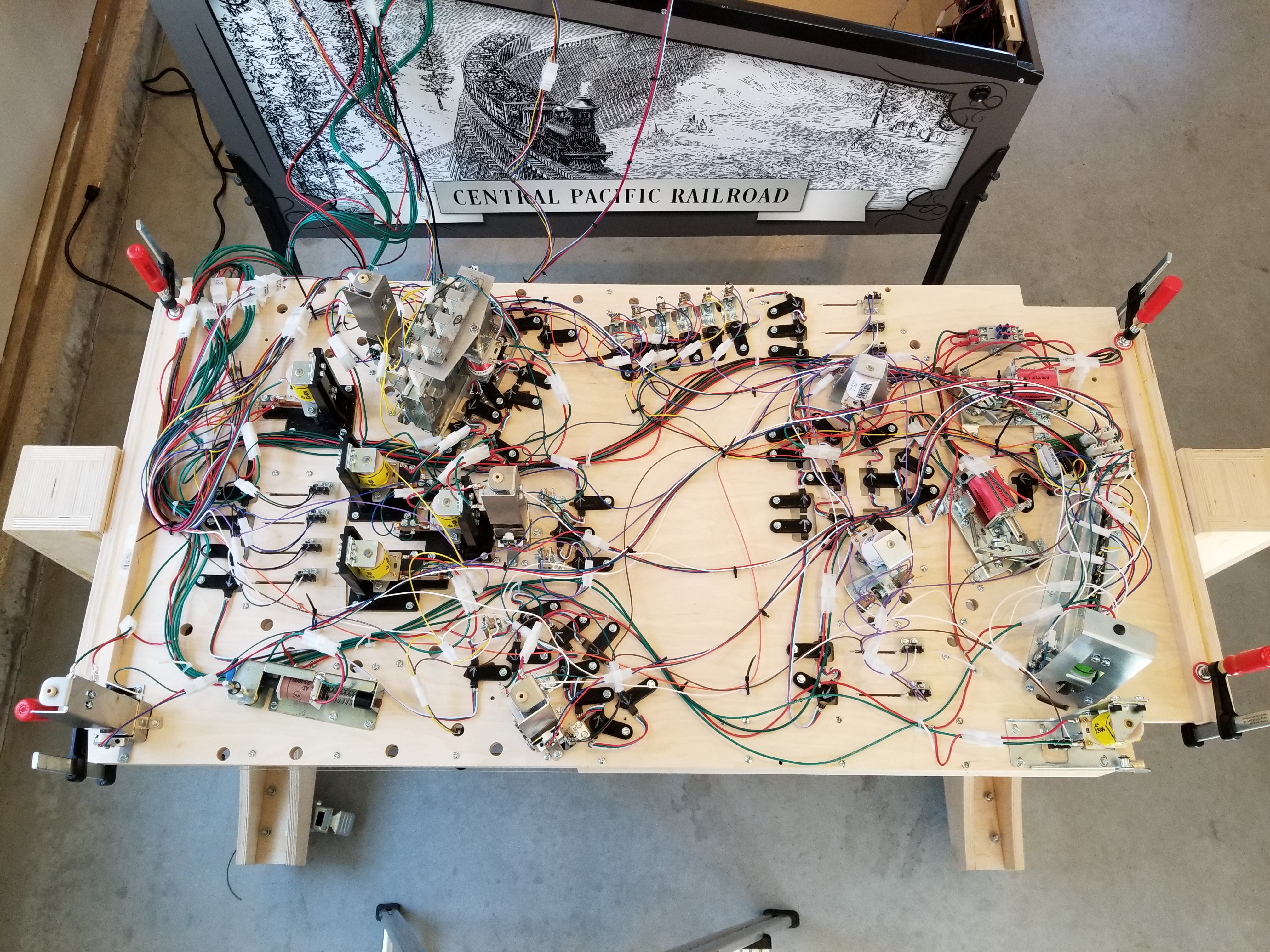
After populating the new control hardware, I began the long process of tearing all of the old wiring out of the cabinet and putting in new wire.
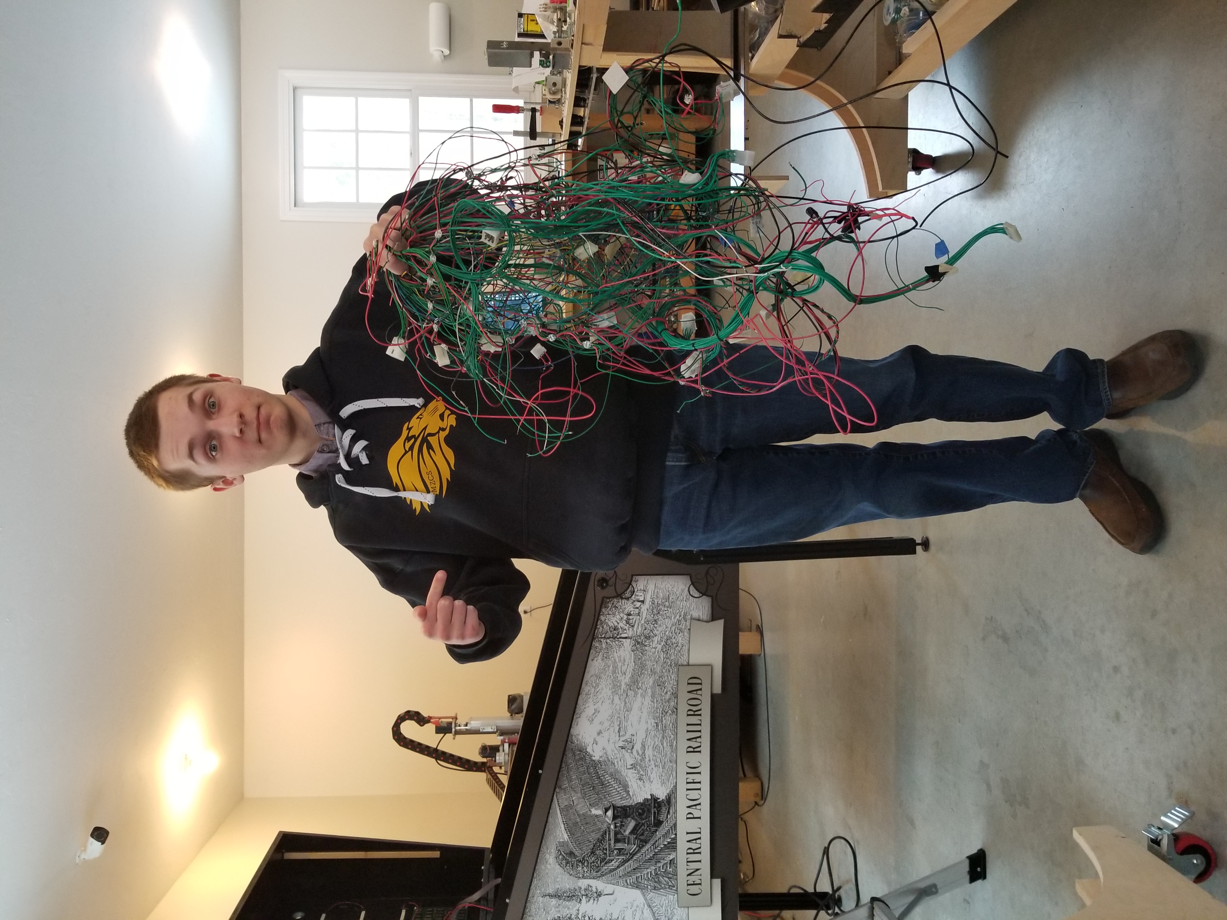

Left: all of the old playfield and cabinet wire; 350 feet of it. Right: power and ground wired to the new hardware.

One of the things I realized that I really needed to do was add connectors to everything. Although it may seem extreme, connectors on every switch are in fact a necessity that you will regret not having.
From there, I paused to check that the beginning of the switch matrix (all of the cabinet switches) was working. On the second revision Pinball Driver Board, I added two connectors in parallel for each part of the switch matrix: one for the cabinet and one for the playfield. That way, I could keep those two parts of the harness "separate" and make folding the backbox down easier.

There's about to be a crazy amount of wire in there.
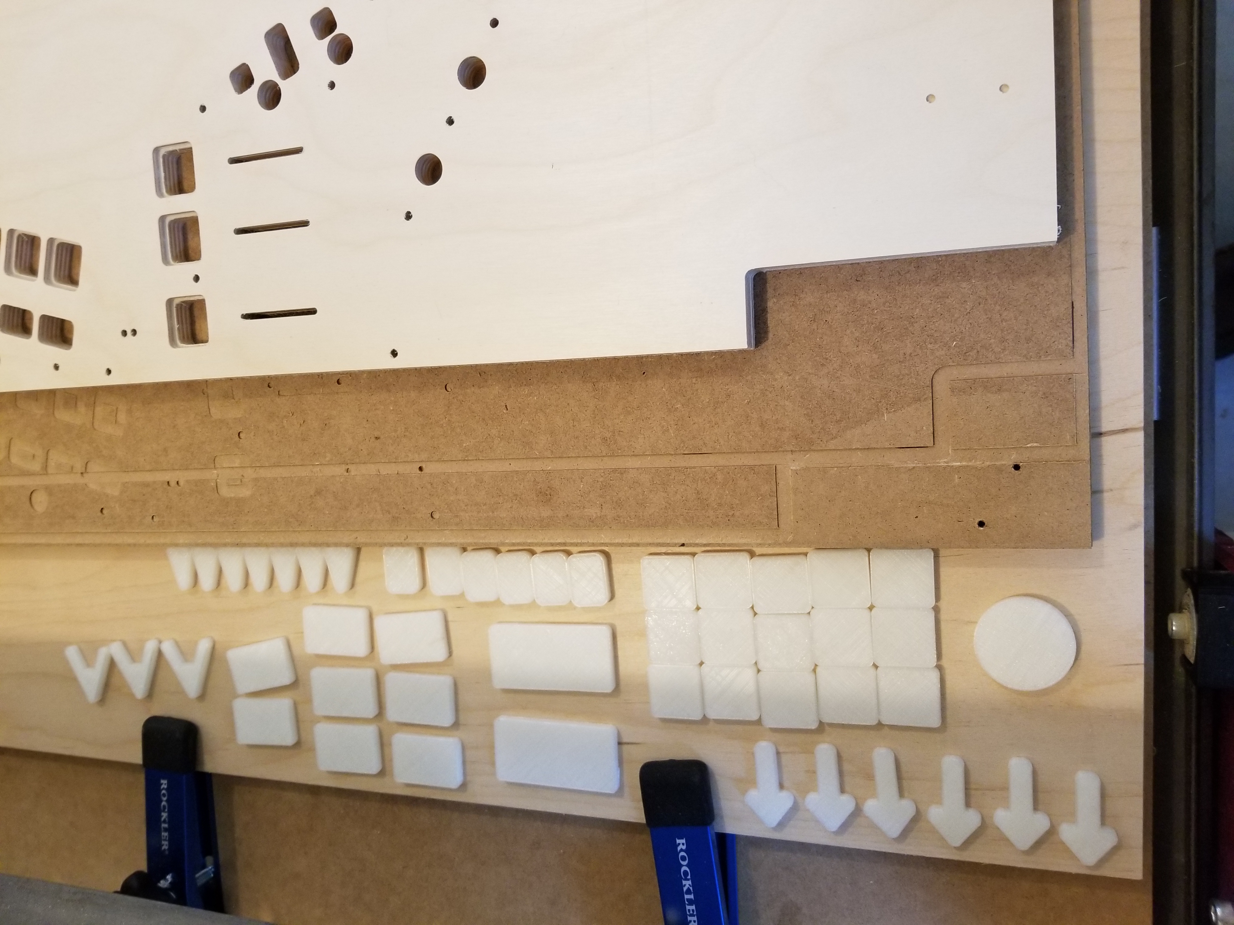
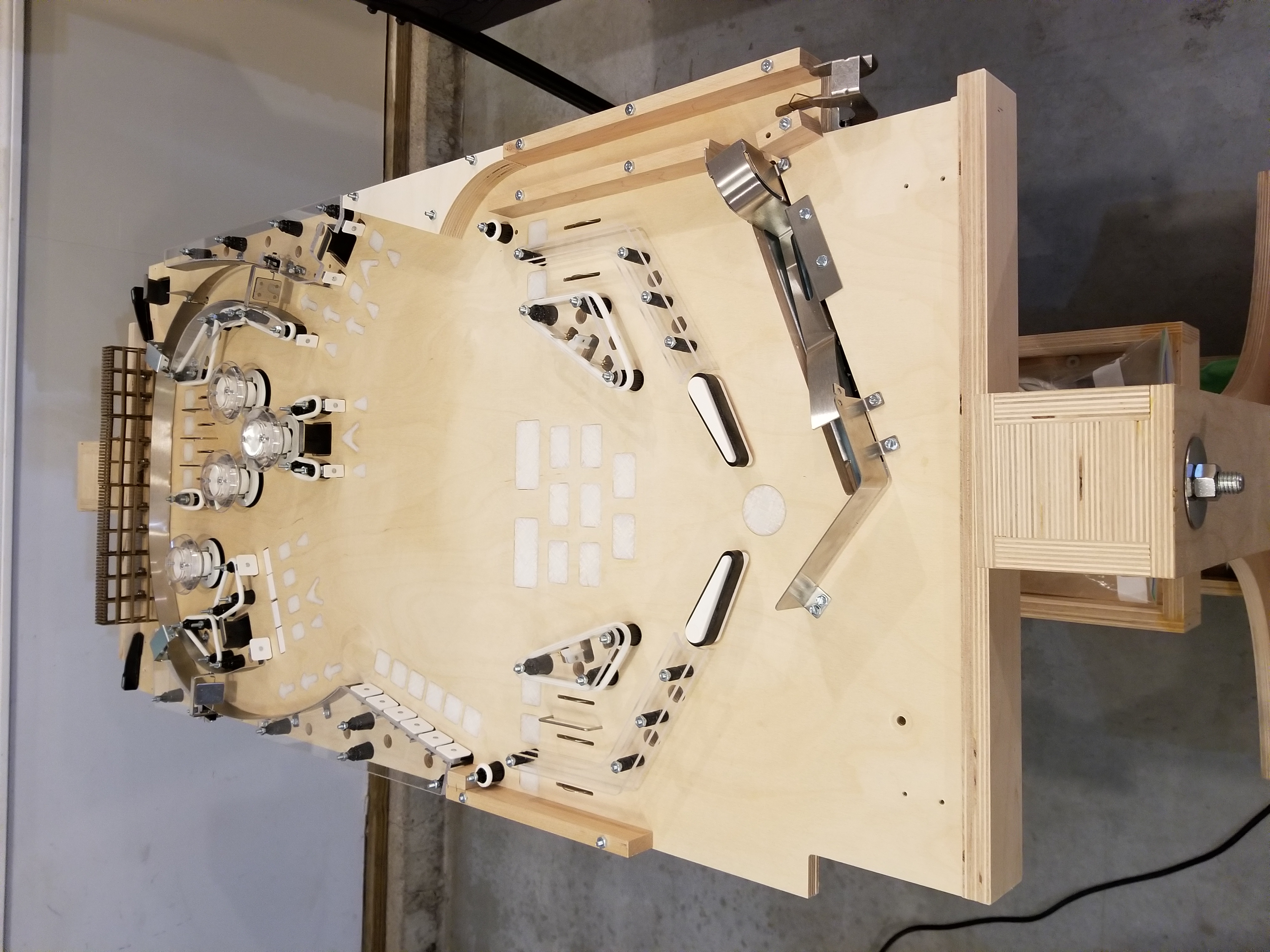
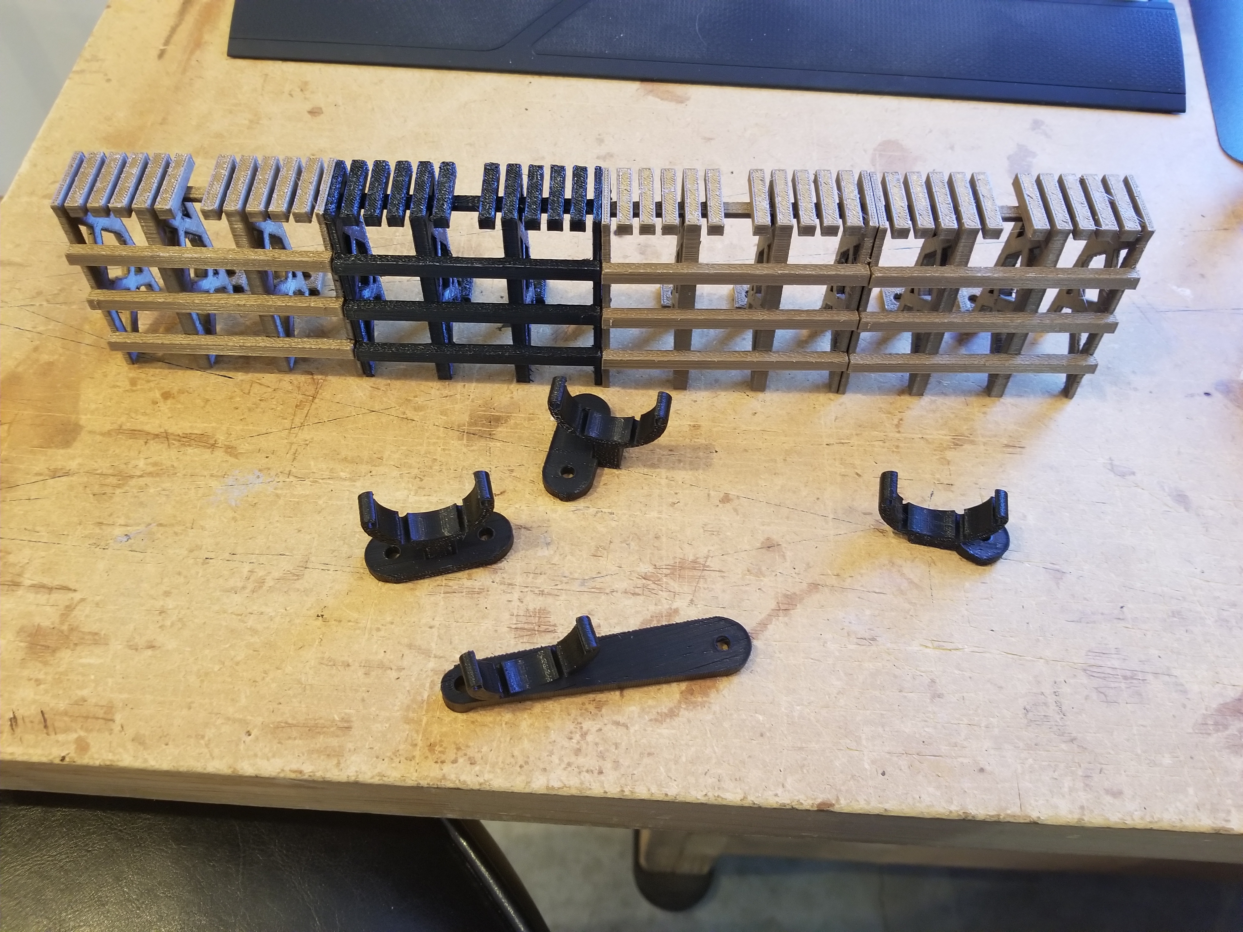
The last thing to do before I began to populate the playfield was to start designing and printing some of new fixtures on the playfield. Remember how I mentioned earlier that the trestle area was pretty empty? Well, that was because I had finally figured out a solution to the layout problem. I would put a VuK under a 3d-printed mountain and have it shoot the ball across a 3d-printed trestle, which would then roll down a ramp to a return lane. Here is the first iteration of the trestle and the right mountain:
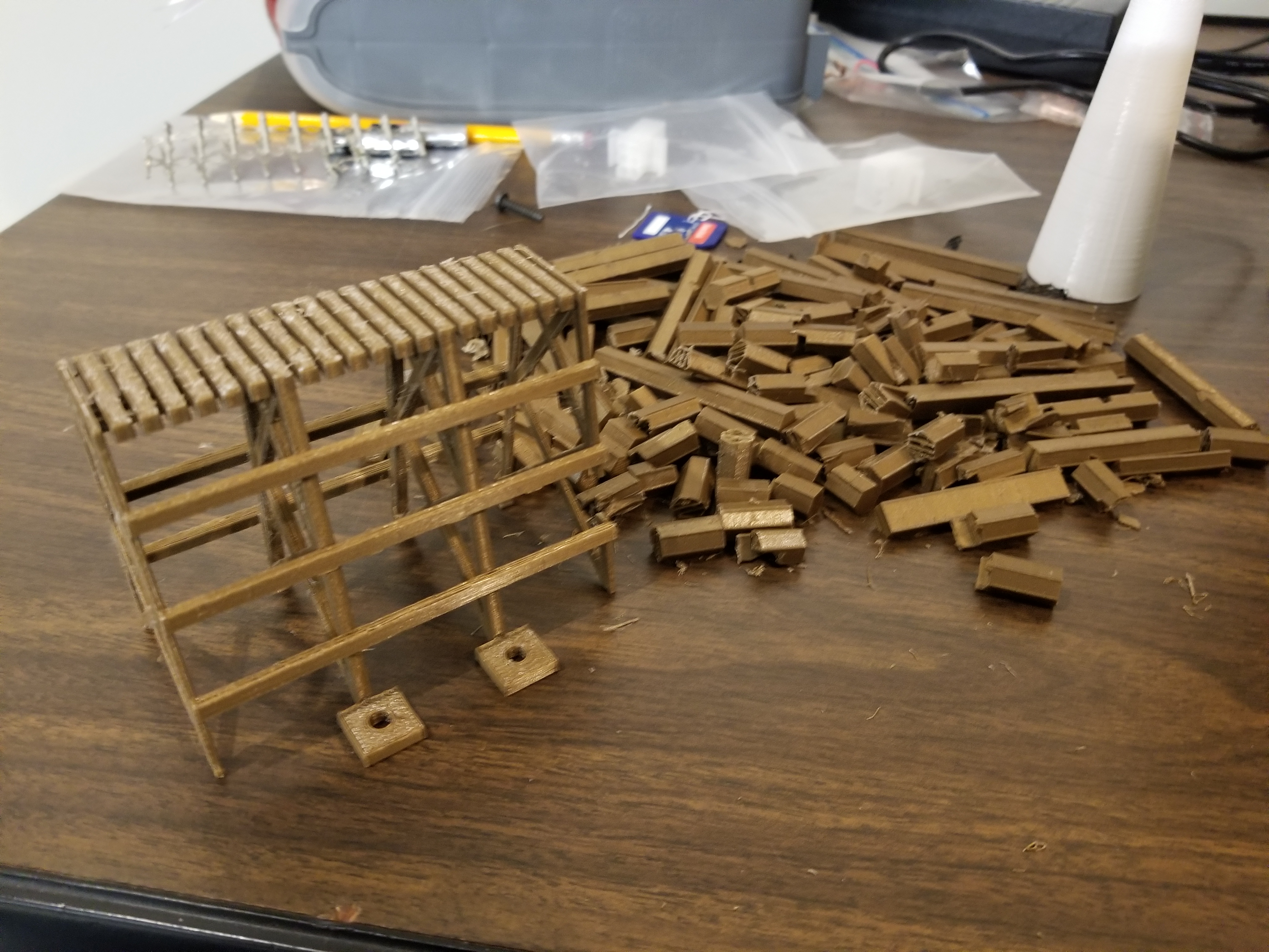
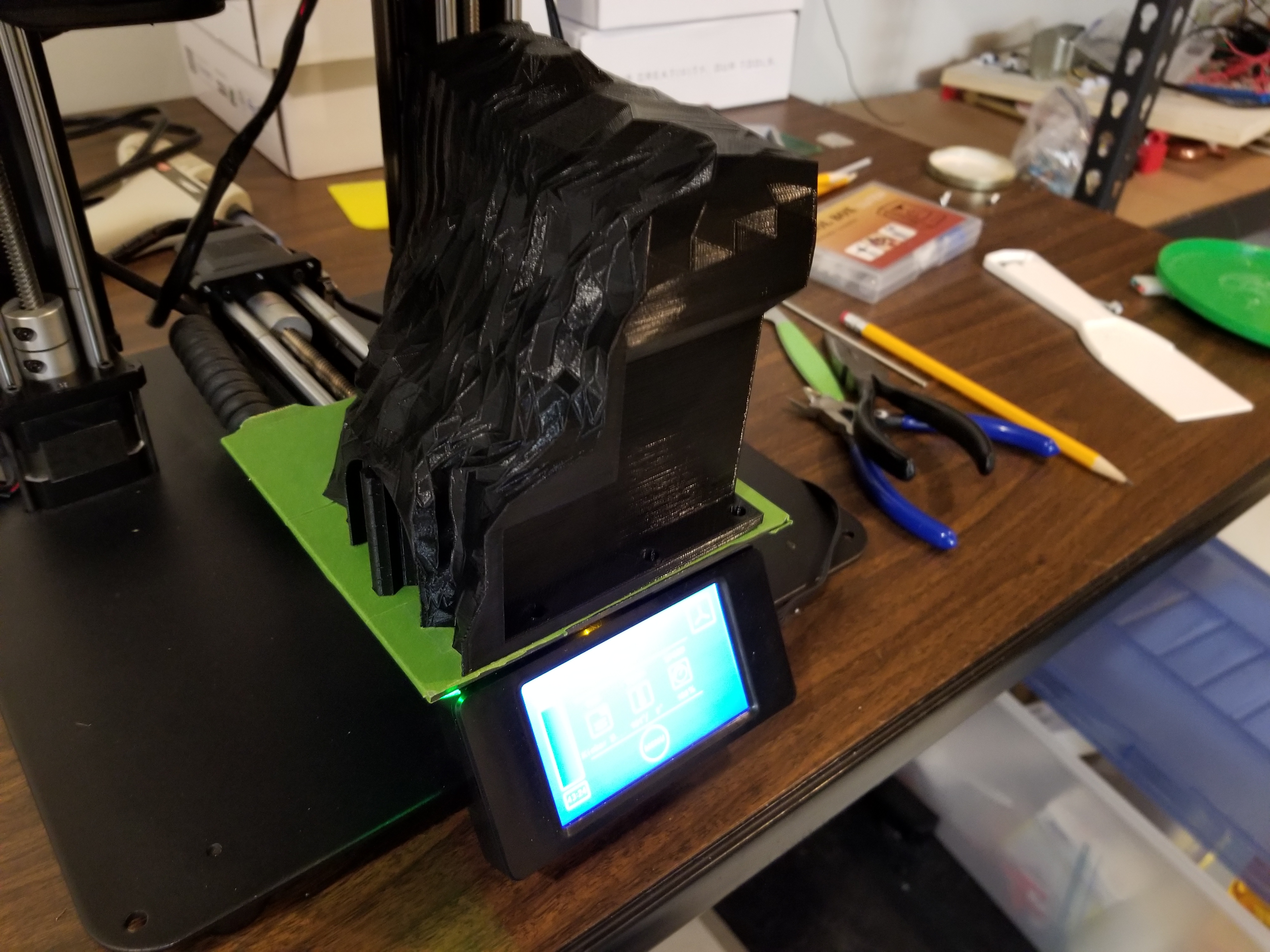
I would end up making significant changes to each of these... and they took about 2 days each to print each time. :/
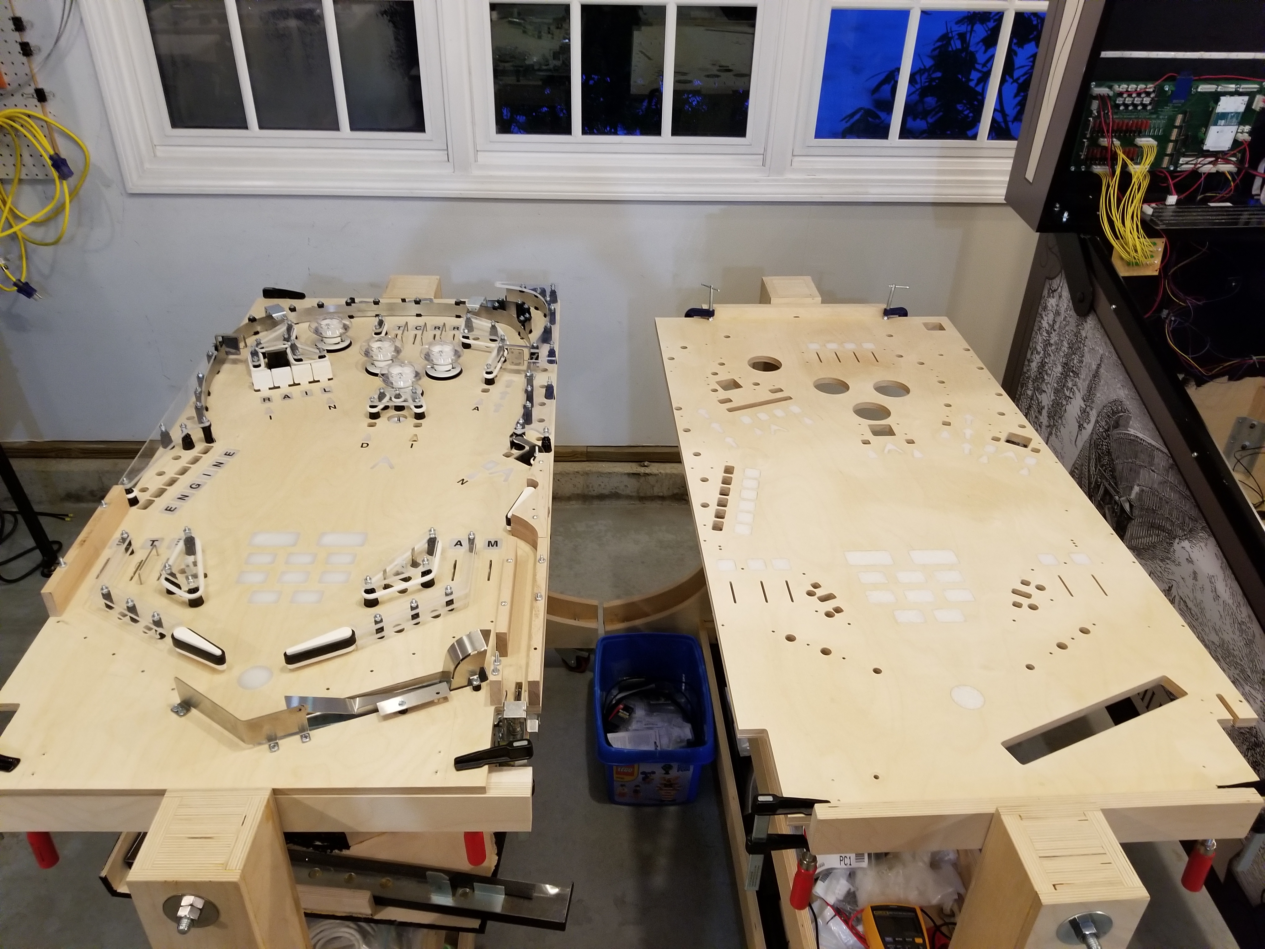
And so I began the process of depopulating the 2nd playfield revision. I commandeered my Dad's playfield rotisserie and made him put his playfield somewhere else so that I could put my two playfields side-by-side and transfer parts between them, although I ended up just removing everything and putting it onto a table before putting it all on the new playfield... Sorry, Dad!

It wasn't long after I began denuding the 2nd playfield revision that I realized I had forgotten an important step... machining the plastics! I did that immediately.

I ended up having to make some changes to these as well.
I also took a picture of all the playfield revisions lined up -- left to right are 1-3.
Populating the playfield wasn't too bad... installing the parts only took about 13 hours.

I had to remove the mountains to clamp the playfield to the rotisserie.
However, that's not all there is to the mountain and trestle area. I had designed some wireform ramps for it and still had to fabricate them. I started by drawing them up in my RHINO playfield file and designed a bunch of convenient 3d-printed clips to snap the rails into.

You can see some of my Dad's early ideas for playfield art on the right.
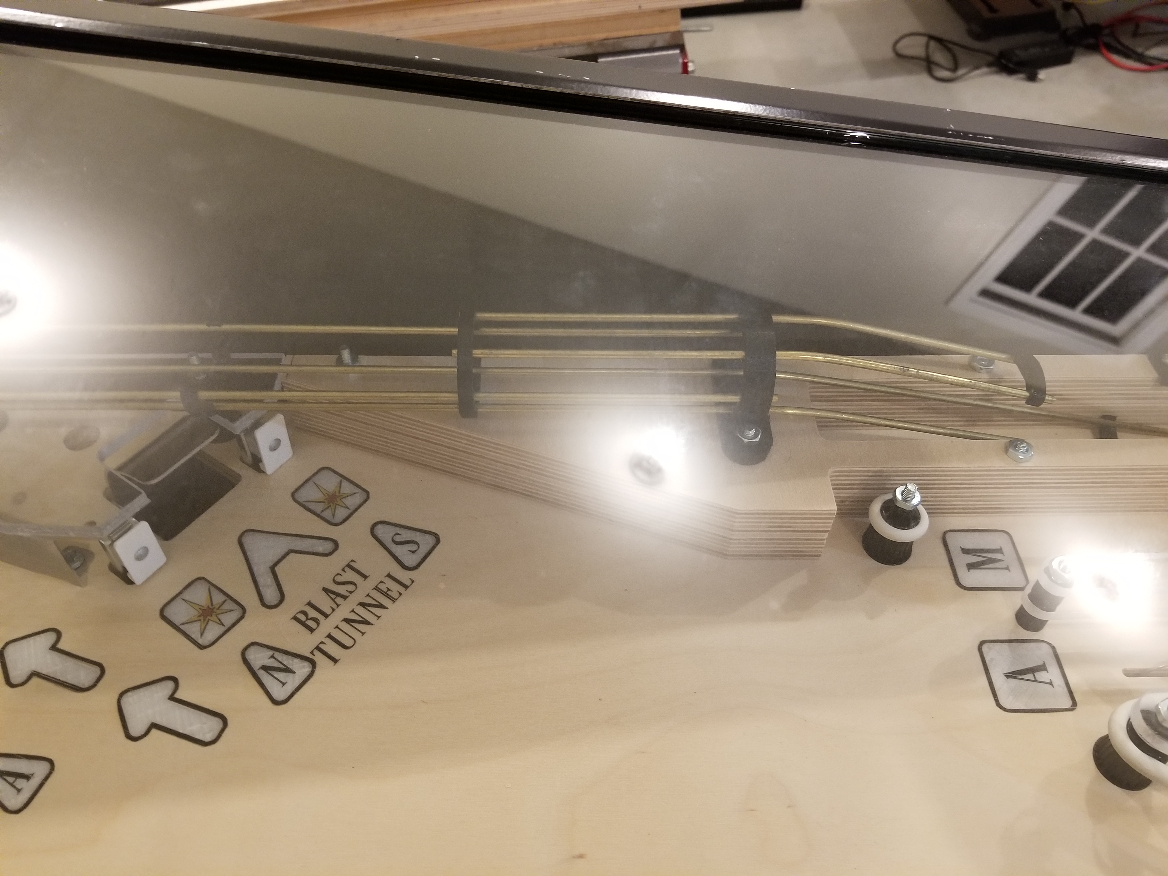
Bending the brass rods for the wireform ramps was much more difficult than I expected. It never occured to me that if I bent a rod into a position, there was a certain amount of it that it would spring back after being bent. Therefore, I had to bend it beyond what I needed to get it bent to where I wanted it. Additionally, maintaining a good grip on the wire and bending it in a single direction were challenging as well.
Although I don't have a picture of it, I printed out a wireframe view of the playfield in RHINO at a 1:1 scale to use for bending the wires. That proved to be very helpful.
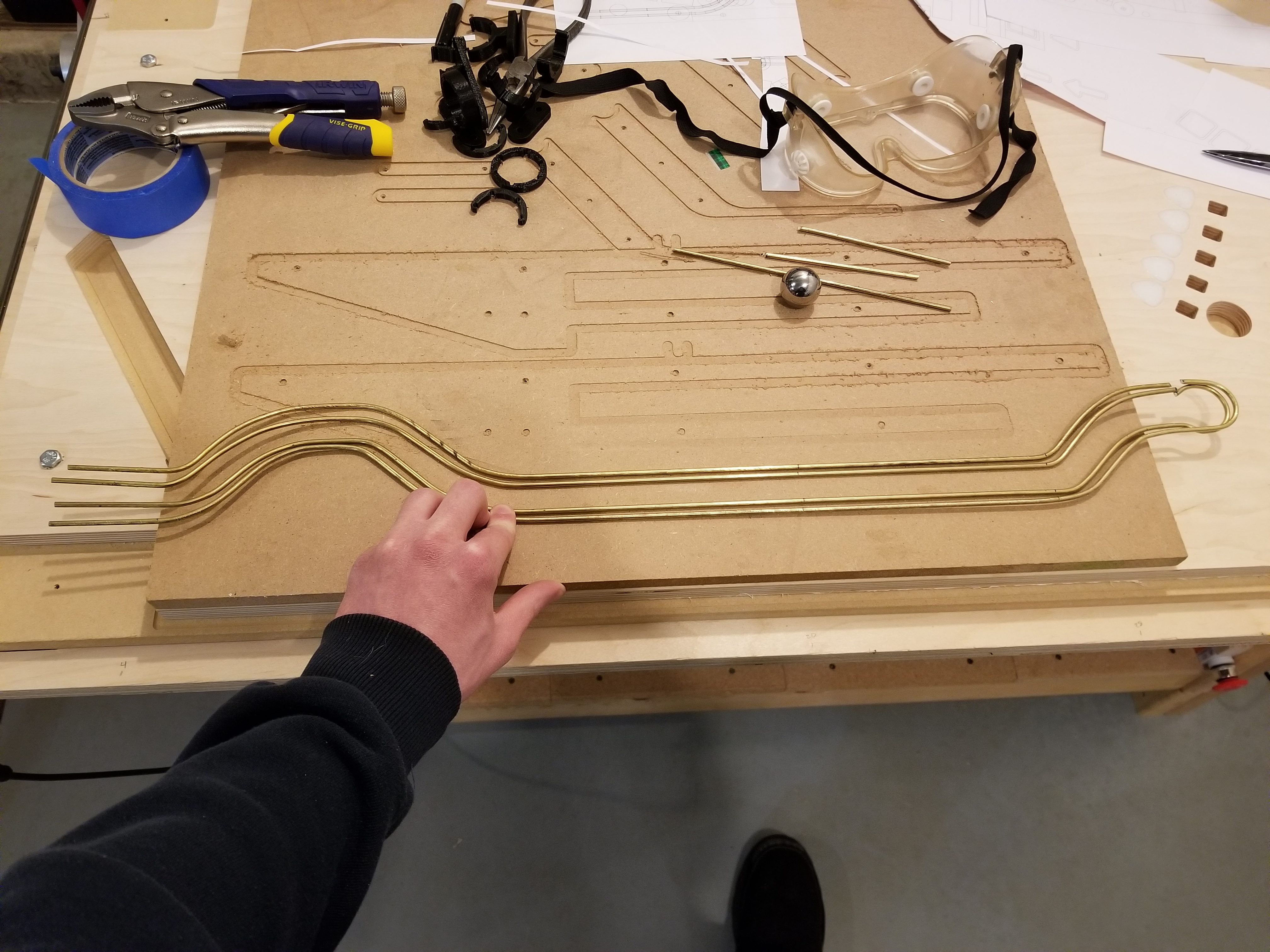
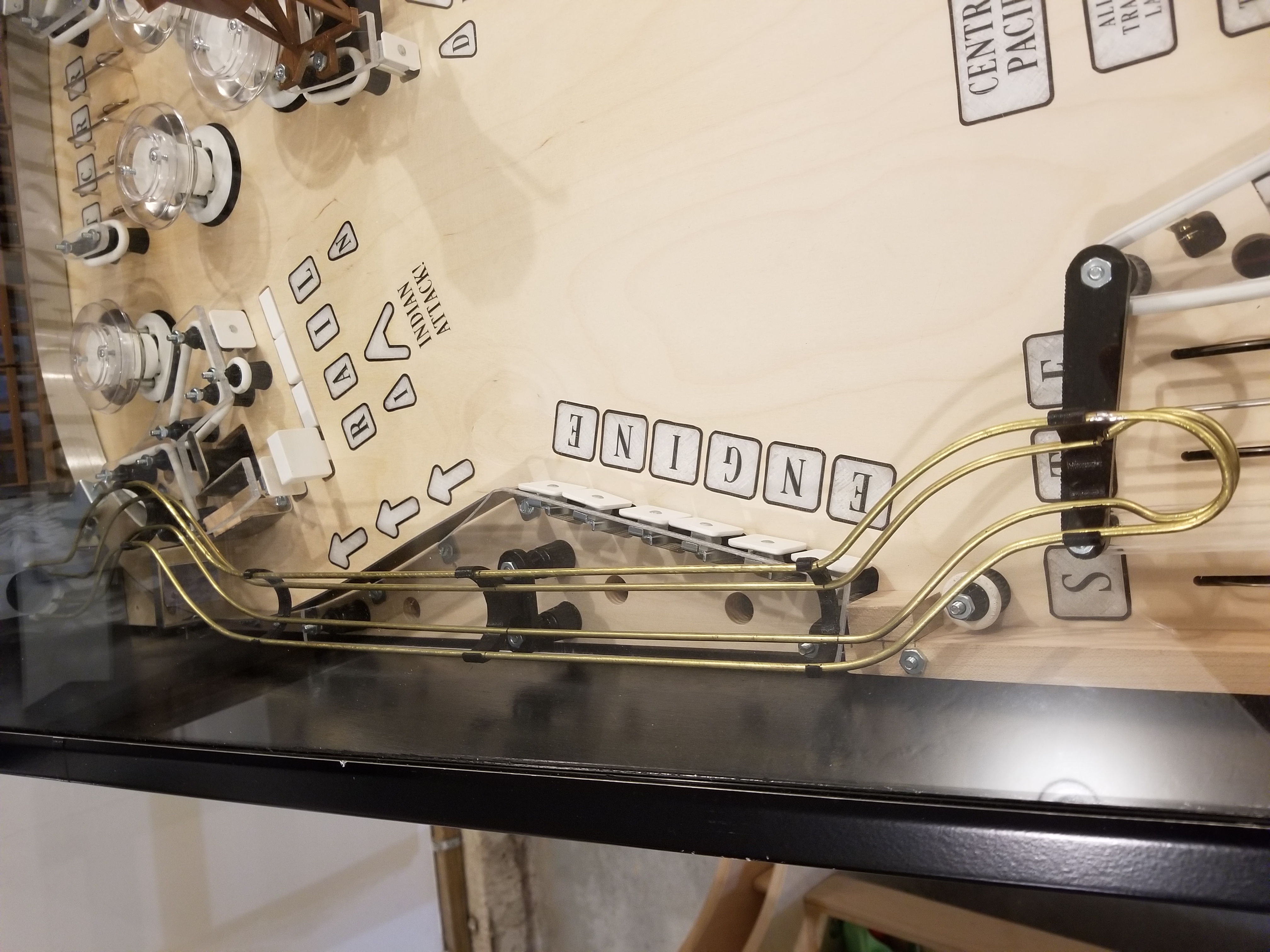
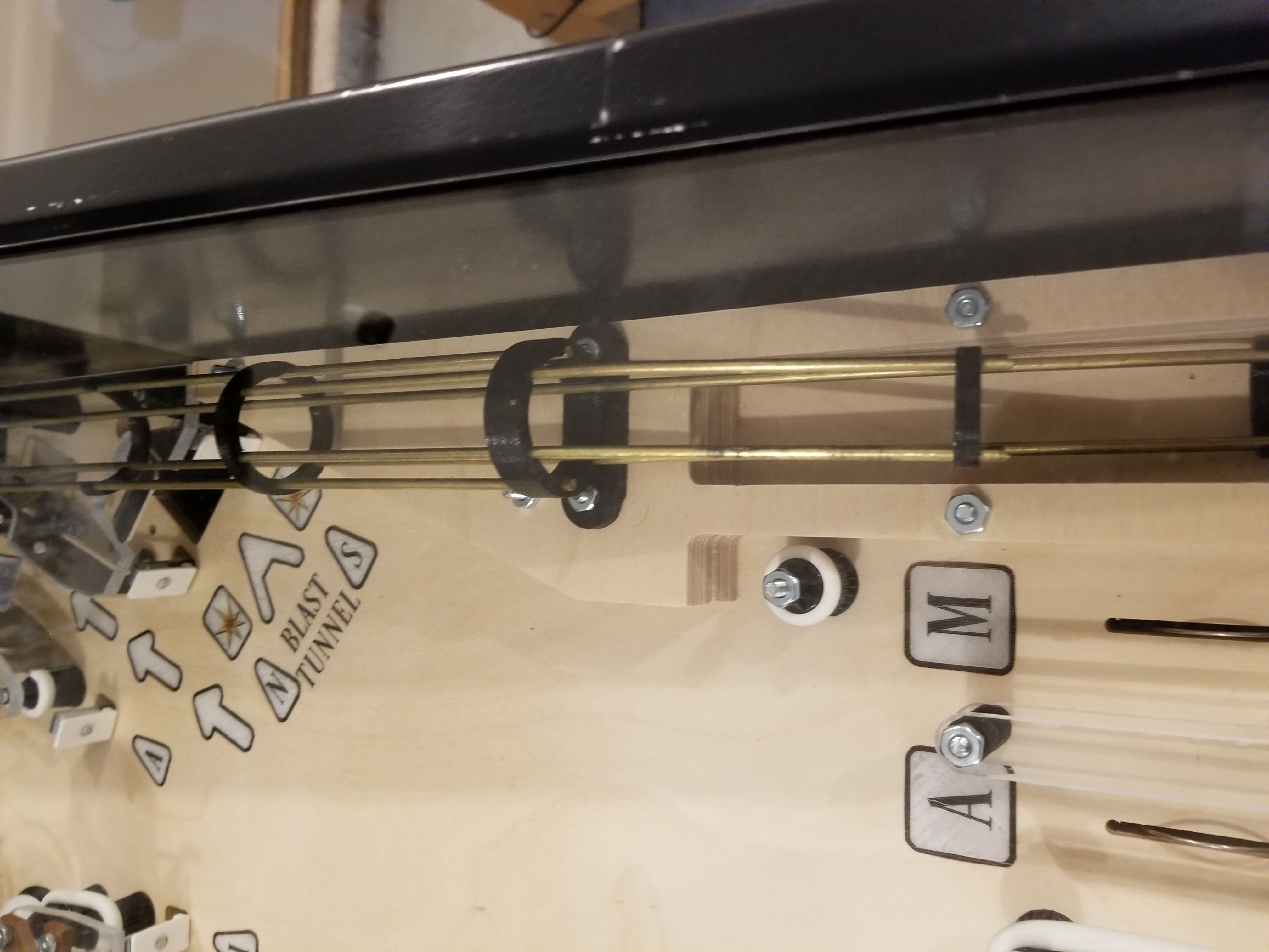
Some of the wire rails I bent.
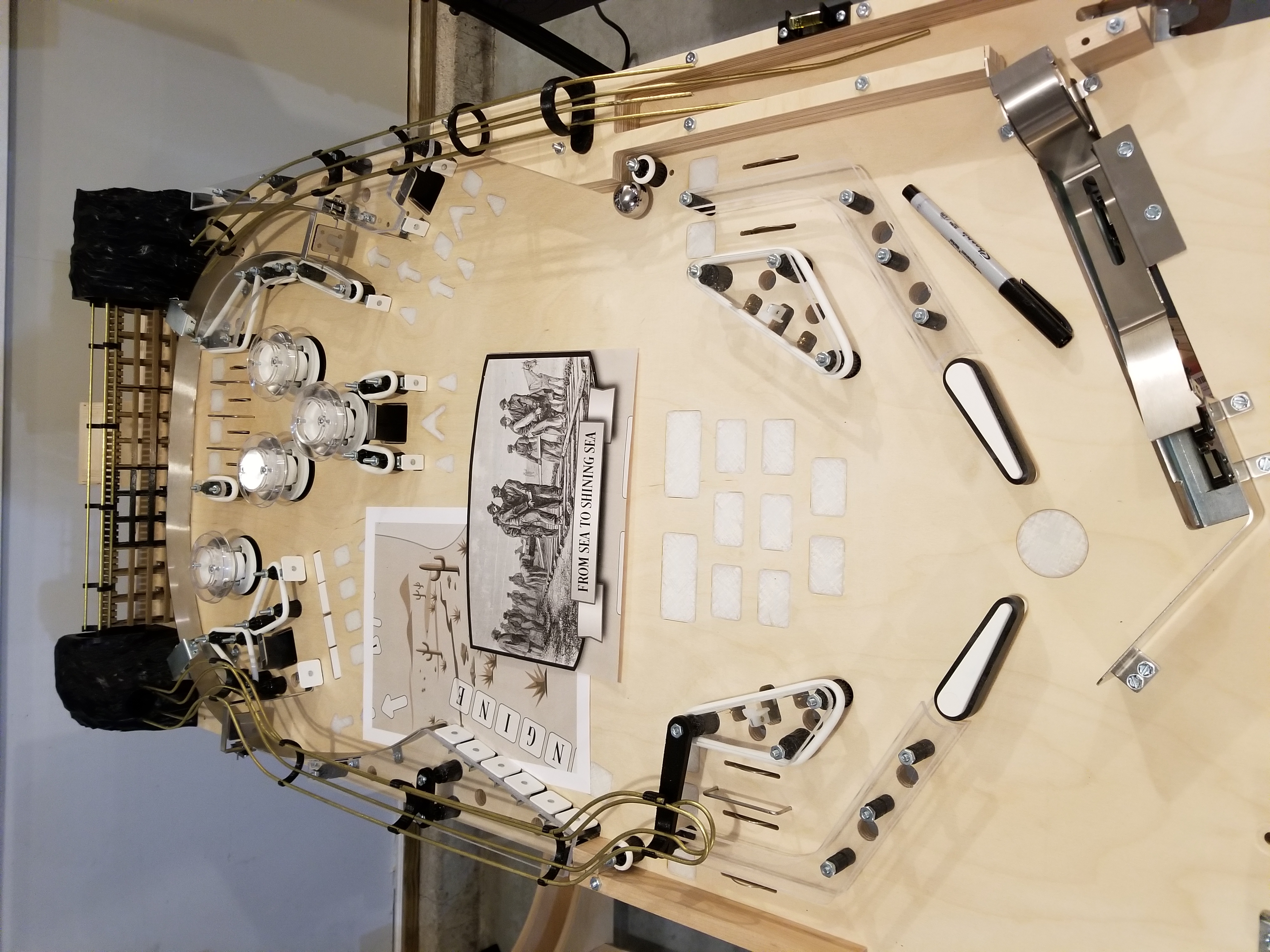
The revision-3 playfield with all of its wire ramps.
It was at this point that I decided to fabricate the 4th playfield revision because I was hoping to be able to have all of the artwork on the playfield before taking it to the school exhibition. Unfortunately, that artwork was not finished yet (and still has not been).
Here is the fourth (and hopefully final) playfield revision:

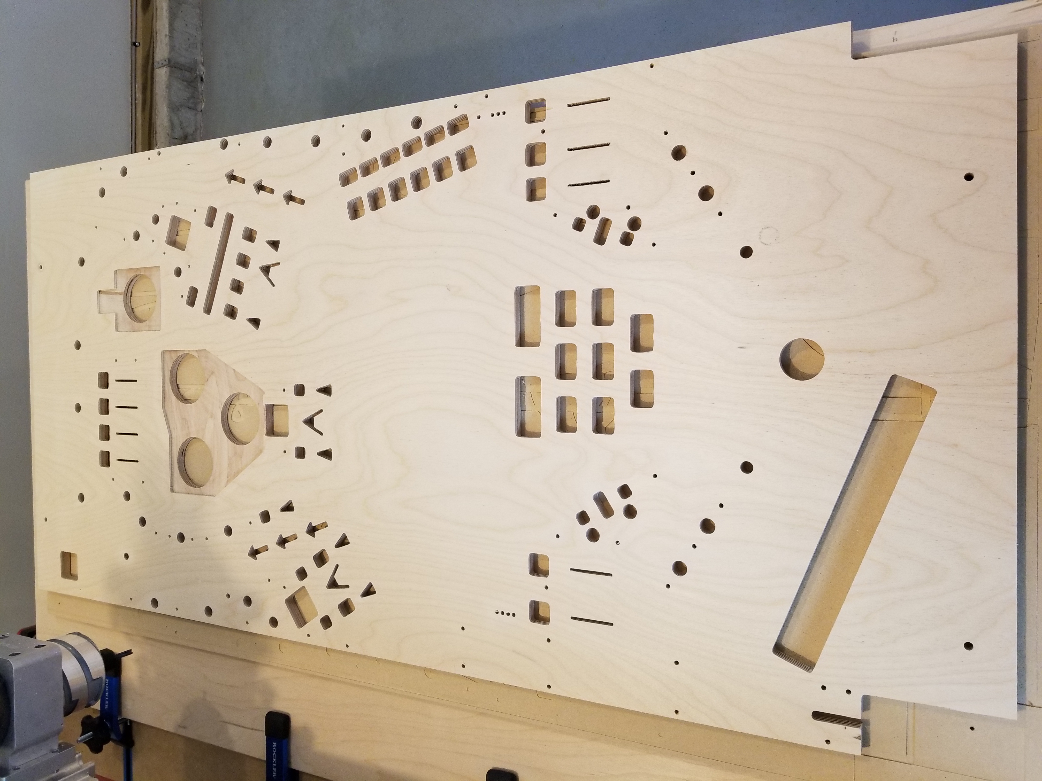
I made playfield revision 4 out of 3/4 inch wood, so I had to machine cutouts for the pop bumpers on the back.
After milling playfield revision 4, I promptly wired up plafield revision 3. It was quite annoying to be unable to do anything with playfield revision 4 since I didn't have artwork yet. After all, I'll have to spend 40 or so hours transferring everything over to revision 4 when it finally gets artwork. However, the playfield can't be printed or clearcoated if it has parts on it, so I had to let it slide.
When I wired up revision 3, I put molex connectors on everything to make it super easy to transfer the wiring harness over. I also planned out every spot where I put a cable mount so I could put them in the exact same spot on revision 4. Furthermore, I put frequent zip ties on all of the wires to keep them in nice bundles. The only way this wiring harness could be improved is if I were to make a wiring harness jig like any pinball manufacturer does. However, for a one-off, it isn't worth it.
I'm still incredibly proud of this harness.

When making this harness, I also put tiny connectors on all of the addressable LEDs. I modified the holders so that they would be able to accomodate these connectors as well. All in all, they turned out great! It made replacing individual LEDs very easy when I had to test the lights.
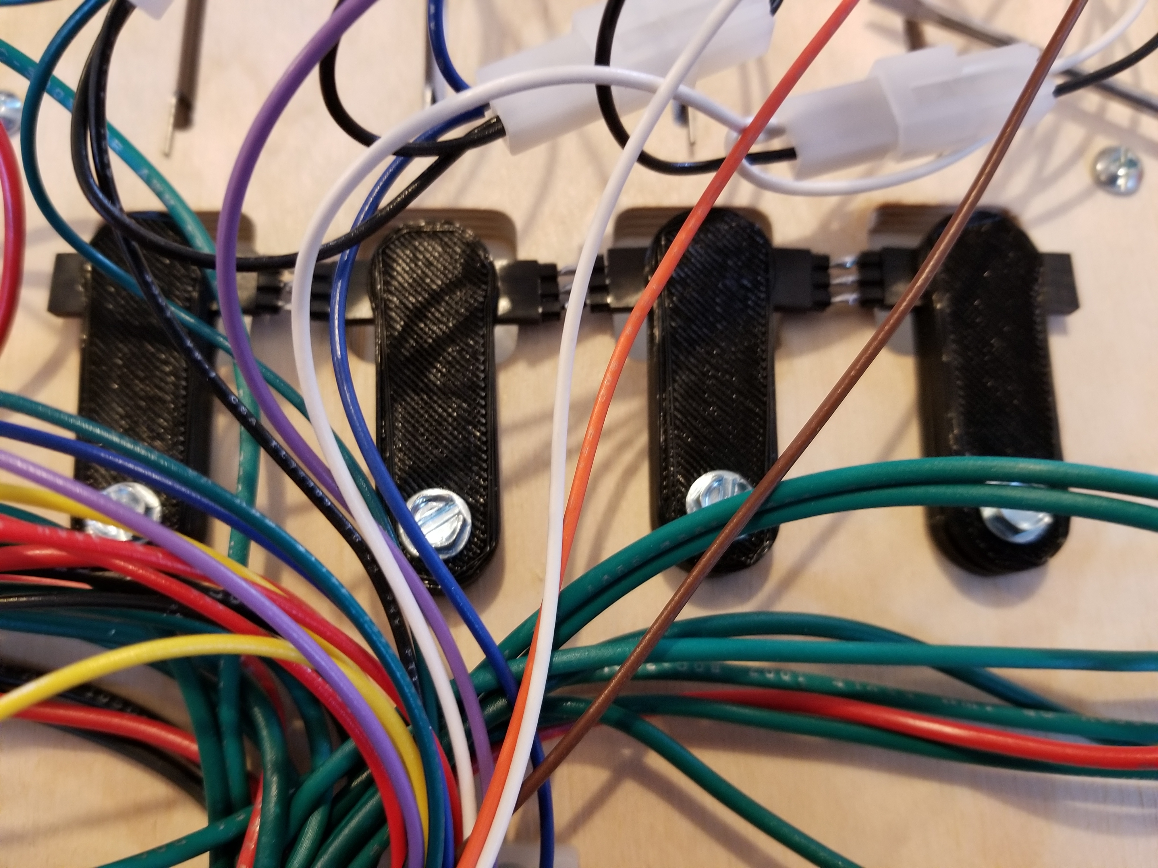
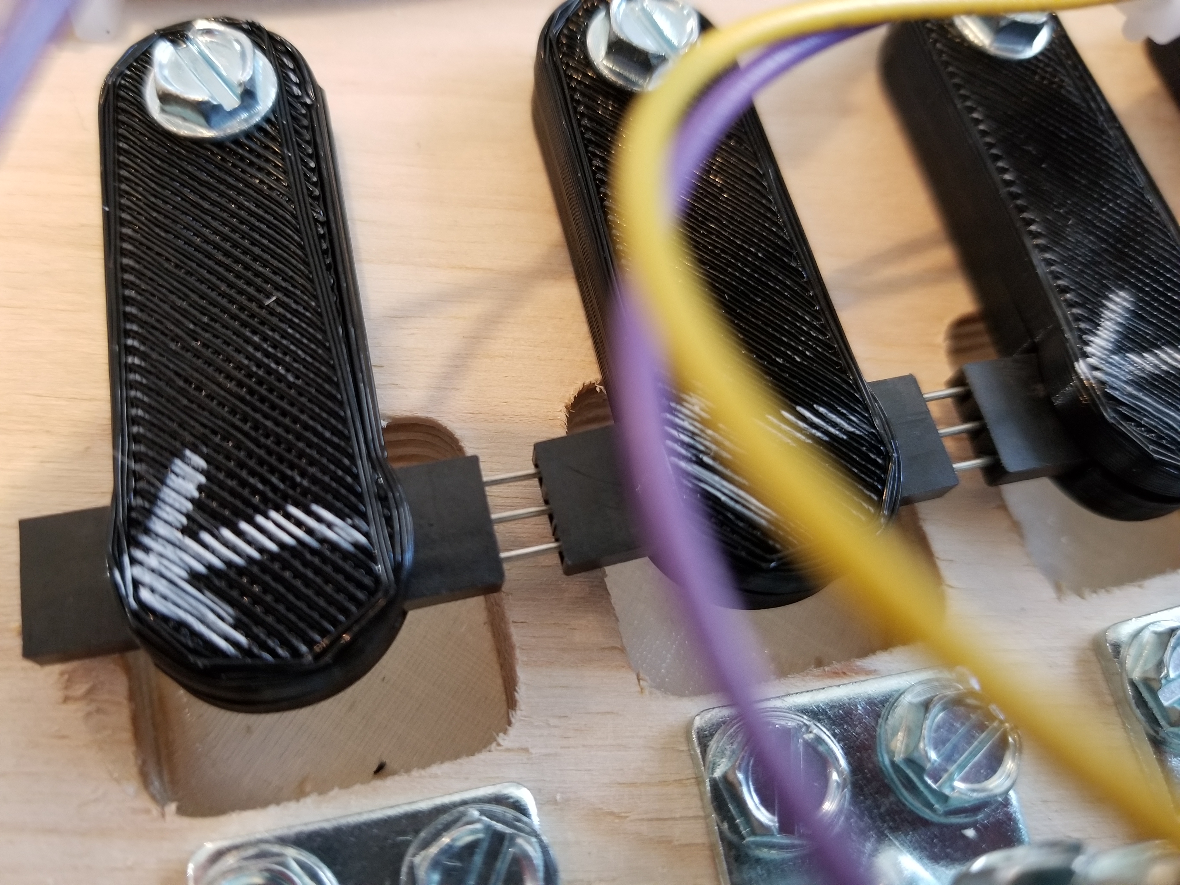
On some lights that were really close together, I had to stick actual wires into the connectors because I couldn't fit the mating connectors in.
At this point, the wiring harness was pretty much finished. Here's a picture with everything.
While testing all the lights:

From here, it was pretty much a matter of programming all the game logic. I ended up rewriting all of the game's main program with multiball support in mind from the getgo, so ball control is much better than the previous version. One suprising challenge was programming the diverter. A diverter is basically a very scaled back flipper assembly. It doesn't even have an EOS switch. When power is applied, a metal plunger is pulled back which actuates a lever, just like in a flipper assembly. However, without a double-wound coil and EOS switch, the low-resistance coil will burn up pretty quickly. To solve this issue, typical games will PWM the coil. However, I could not find a ratio of on/off that would hold the diverter open without making a nasty rattling noise. I'm not sure if my hardware was unable to toggle it fast enough. After trying a bunch of resistors, I just gave up and mounted a flipper assembly into it. It worked just fine.
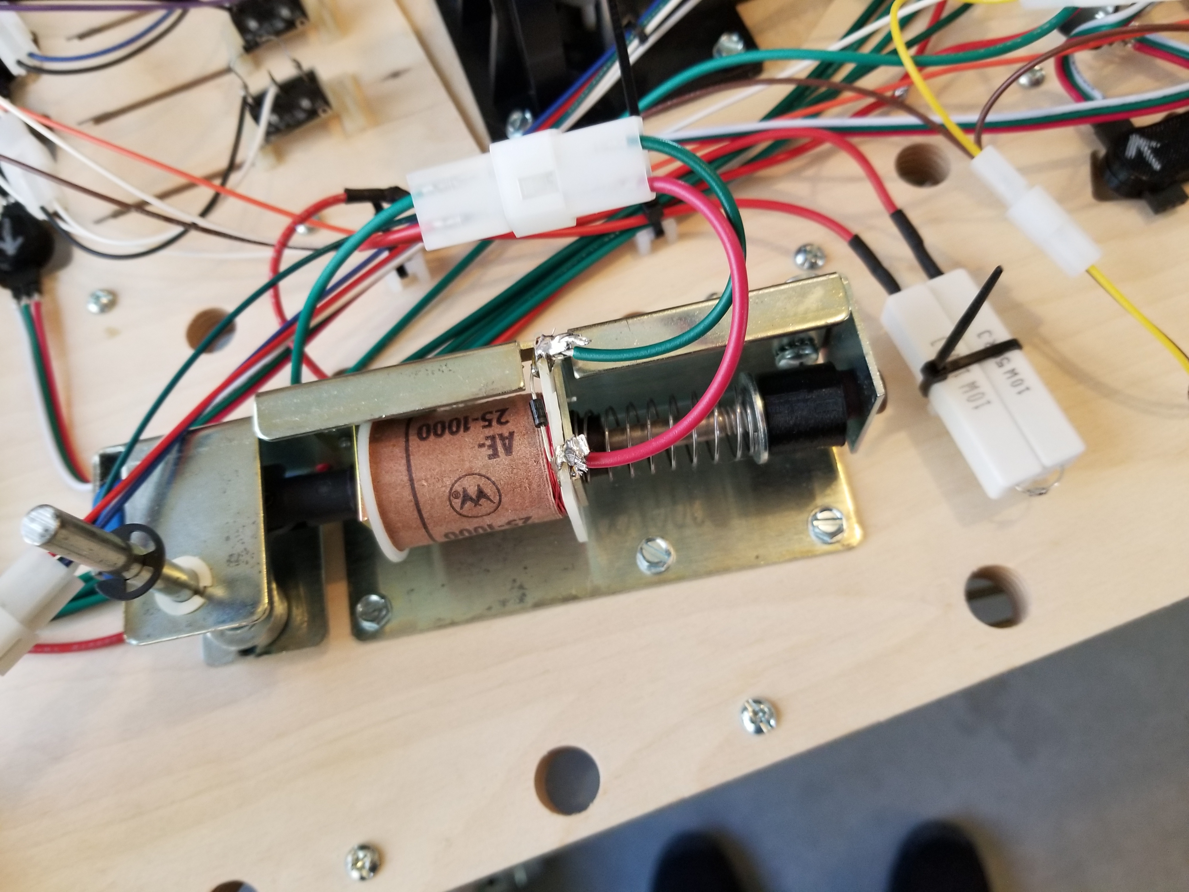
The diverter. NOS replacement for a Judge Dredd game. Pictured are some ceramic resistors wired inline to try and fix the issue.
With the exhibition coming up soon, my Dad and I figured it would be good to indicate what each light on the playfield represented. He drew up some nice stickers to put over the inserts. They were quite well done:
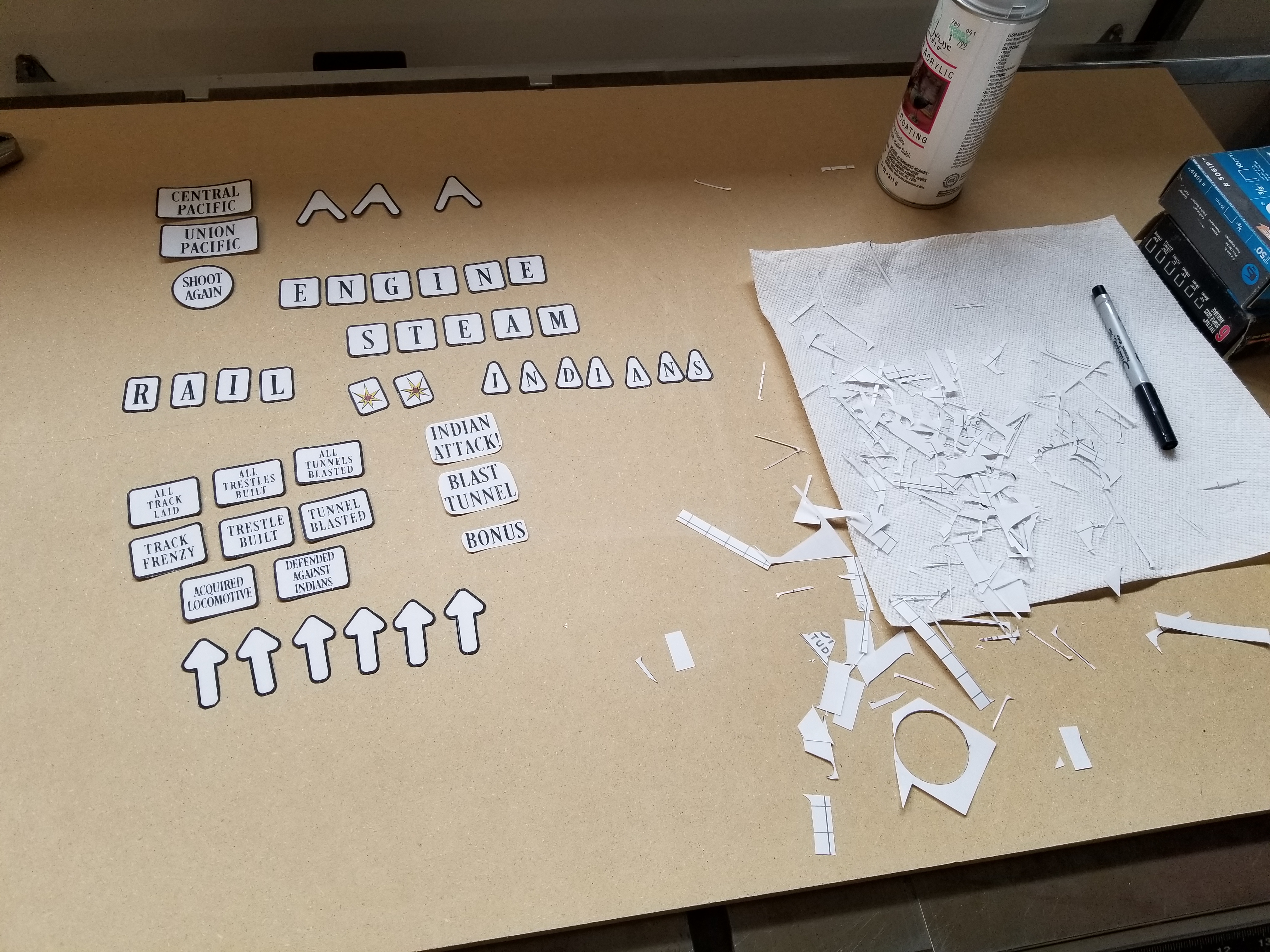
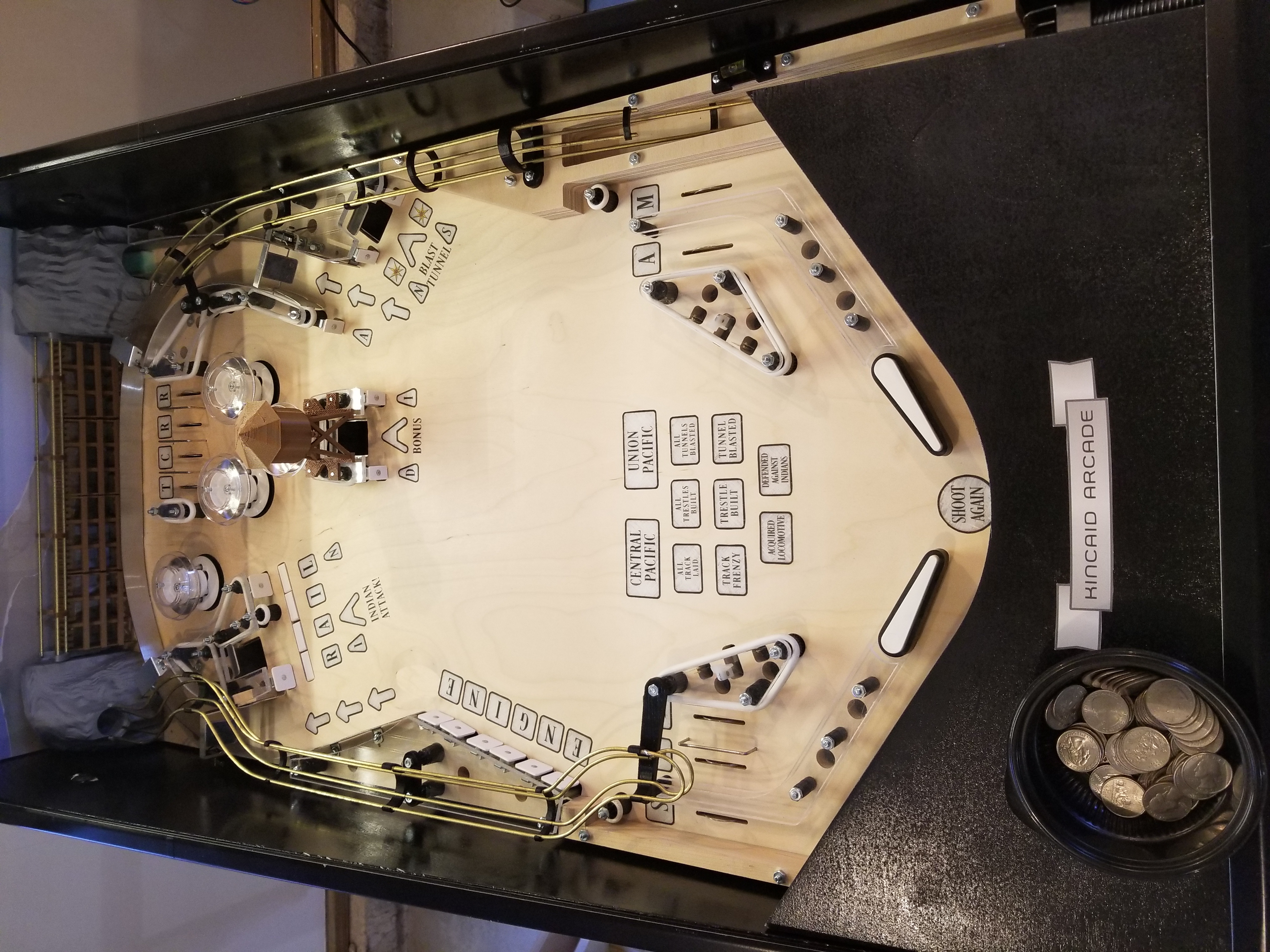
The Golden Spike Rev-3 playfield
I have a funny anecdote that happened about this time in the project. There was a bird, which I will simply call Kamikaze. Kamikaze was... special. Every day, for about a week, while I was in the garage working on Golden Spike, Kamikaze would incessantly dive-bomb the window right behind Golden Spike. Kamikaze would do this for two or three hours each day. I don't know how he did it. Eventually, I just started tuning him out. My dad and I frequently wondered aloud when we'd hear the last of that bird. A week later, we did. I hope he didn't die... I was getting kinda fond of his antics.
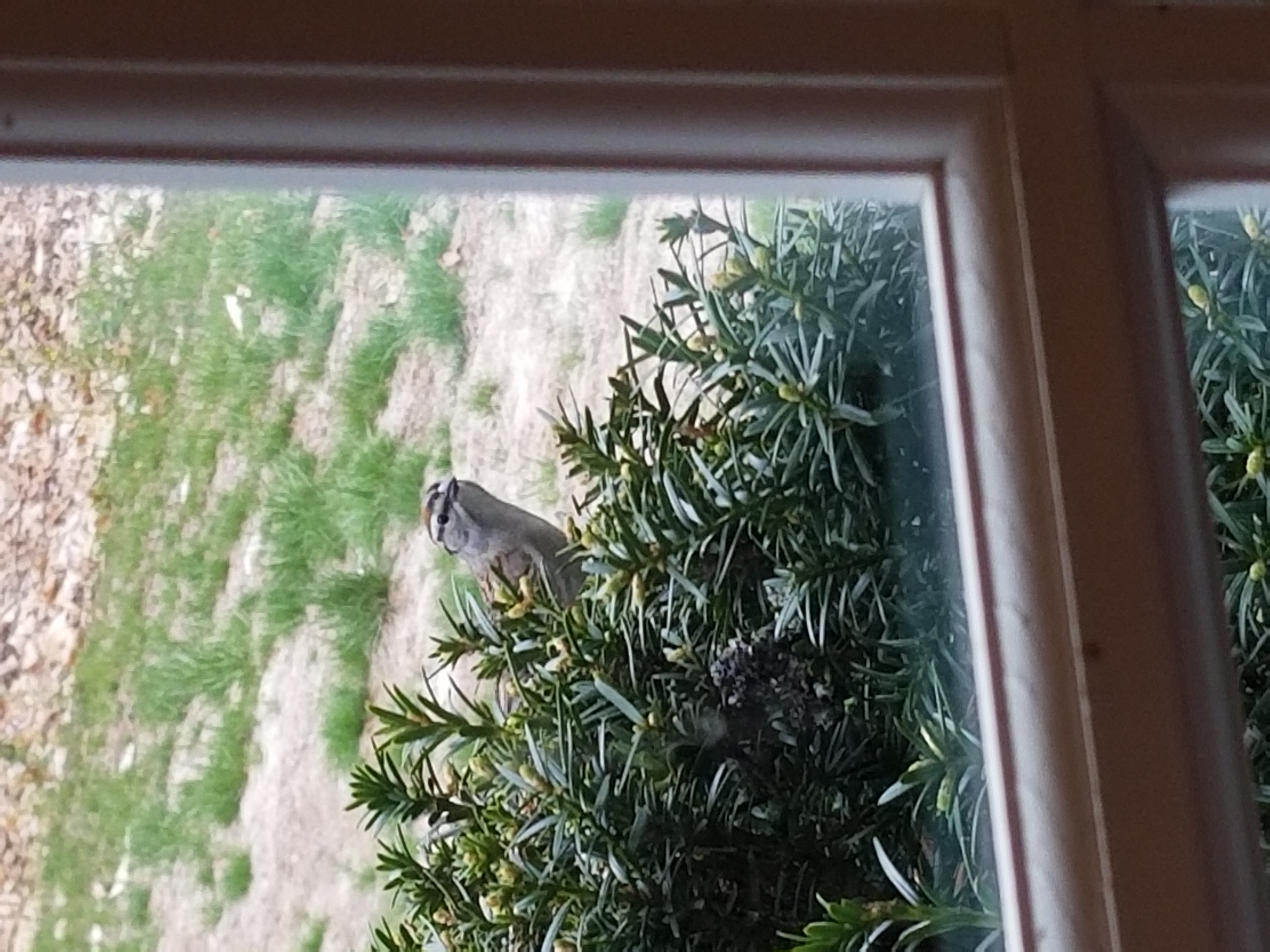
I have so many images of Kamikaze smacking into the glass.
Anyway, once those stickers were applied to the playfield, Golden Spike was finished. I packed it up into a U-haul and brought it to the school exhibition. I was quite disappointed that the parents were unable to see it due to Covid limiting the exhibition, but it was at least very fun to watch the elementary kids play it.
Here's a video of the game playing:
Misc. Images


This page was published 8/7/2019
This page was last updated 1/5/2022
Spelling, grammar, and readability corrections.